Hi,
First post on the forum, and seeking a bit of advice. 🙂
As a first attempt at building a valve amplifier, with an aim of learning more about valves in general, I've built a version of Pointdexter's Audio Tropic 6v6 musical machine.
It's up and running, adjusted as per the design, and various threads from back in the day. Sounds nice, and I'm quite happy with it. Doesn't hum, hasn't caught fire, arced over or anything else amusing. 😀
I've just been doing a few measurements to see what it's actually turned out like; I've no more fancy test equipment than a cheap multimeter, Hantek USB scope, and REW.
I should add that I aimed to build this as cheap as possible, primarily because I wasn't entirely sure I'd get it to work. So it's a lab experiment rather than aimed for perfection like some of the lovely builds on the forum.
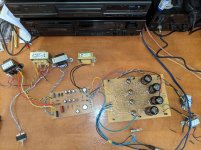
I designed the board trying to keep the input audio route straight and the heaters away from the input side as far as possible. Laser transfer and etched at home effort. 😉
I redesigned the PSU to take advantage of the most cost-effective transformers I could get hold of shipped to/in the UK in a sensible timeframe. More relevantly I'm also running extremely cheap 100v line transformers as OPTs. This was inspired by http://home.alphalink.com.au/~cambie/6AN8amp/M1115.htm ... 😀
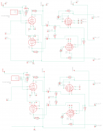
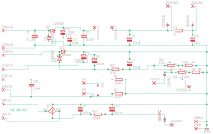
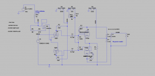
I've attached Poinz' schematic here (again), along with my schematic, a few photos and some measurements.
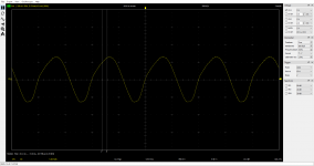
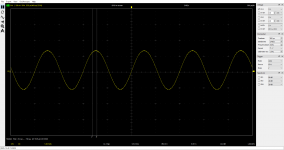
The issue I'm seeing is that I can drive the amplifier into clipping at 1khz just beyond a measured output power of 2.5w, which seems on the early side.
I'm assuming the bass rolloff I'm seeing is from the tiny OPTs. The -3db point at 1W is around 44hz, and at full power, more like 56hz. I'm okay with that, so long as it's the OPT causing it. Limitations are fine! 🙂
It makes about 5.5w into 8ohm, at 1khz flat out. That's for a 2v measured p2p input. Haven't tried driving it harder, as it's already firmly clipping at that point.
Basically wondering if what I'm seeing power/clipping wise is about right?
Cheers! Paul
First post on the forum, and seeking a bit of advice. 🙂
As a first attempt at building a valve amplifier, with an aim of learning more about valves in general, I've built a version of Pointdexter's Audio Tropic 6v6 musical machine.
It's up and running, adjusted as per the design, and various threads from back in the day. Sounds nice, and I'm quite happy with it. Doesn't hum, hasn't caught fire, arced over or anything else amusing. 😀
I've just been doing a few measurements to see what it's actually turned out like; I've no more fancy test equipment than a cheap multimeter, Hantek USB scope, and REW.
I should add that I aimed to build this as cheap as possible, primarily because I wasn't entirely sure I'd get it to work. So it's a lab experiment rather than aimed for perfection like some of the lovely builds on the forum.
I designed the board trying to keep the input audio route straight and the heaters away from the input side as far as possible. Laser transfer and etched at home effort. 😉
I redesigned the PSU to take advantage of the most cost-effective transformers I could get hold of shipped to/in the UK in a sensible timeframe. More relevantly I'm also running extremely cheap 100v line transformers as OPTs. This was inspired by http://home.alphalink.com.au/~cambie/6AN8amp/M1115.htm ... 😀
I've attached Poinz' schematic here (again), along with my schematic, a few photos and some measurements.
The issue I'm seeing is that I can drive the amplifier into clipping at 1khz just beyond a measured output power of 2.5w, which seems on the early side.
I'm assuming the bass rolloff I'm seeing is from the tiny OPTs. The -3db point at 1W is around 44hz, and at full power, more like 56hz. I'm okay with that, so long as it's the OPT causing it. Limitations are fine! 🙂
It makes about 5.5w into 8ohm, at 1khz flat out. That's for a 2v measured p2p input. Haven't tried driving it harder, as it's already firmly clipping at that point.
Basically wondering if what I'm seeing power/clipping wise is about right?
Cheers! Paul
Attachments
-
 6v6_pc_schematic.png43.8 KB · Views: 491
 -
 PXL_20201223_102850848.jpg1,013.7 KB · Views: 261
 -
 PXL_20201223_103022177.NIGHT.jpg973.9 KB · Views: 206
 -
 100hz_full_power_clipping.png56 KB · Views: 118
 -
 100hz_before_clipping.png55.6 KB · Views: 122
 -
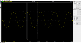 1khz_in_clipping_full_power.png57.9 KB · Views: 119
 -
 1khz_before _clipping.png56.3 KB · Views: 378
 -
 frequency_left_replacement_valve.jpg192.6 KB · Views: 403
 -
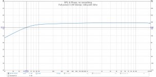 Full power 4.5W Sweep -3db point 56hz.jpg159.6 KB · Views: 449
 -
 musical_machine_2007.GIF23.2 KB · Views: 493

Approx. 6 WPC is correct for a 6V6 "Musical Machine". That 5.5 W. number is definitely close enough.
Cheers Eli, good to know it's in the ballpark. Should I expect it to start clipping as early as it does?
Deja Vu.
Those diodes between the 330 Ohm resistors and the 6V6 screens are not needed.
The 6V6 tubes are not operating at any condition that needs them.
I just hate to see amplifier schematics with extraneous parts.
Then, so many repeat the same error.
Those diodes between the 330 Ohm resistors and the 6V6 screens are not needed.
The 6V6 tubes are not operating at any condition that needs them.
I just hate to see amplifier schematics with extraneous parts.
Then, so many repeat the same error.
Deja Vu.
Those diodes between the 330 Ohm resistors and the 6V6 screens are not needed.
I did read some of the previous discussion surrounding those diodes. However, as I'm not clever enough to understand what they're doing (or not), and likewise to sift the discussions for the truth, and given Pointdexter presumably knows rather more than me, I stayed with his design in that area as it was written.
I assume they're not doing any harm, despite being extraneous?
PC
Paul & 6A3,
There is information here (Section 2):
Tubes
And discussions here:
D3a - diode between screen & plate (triode) ?
I do know that K&K Audio uses the modification on some of their designs and has noticed a quality that is subjectively more triode in nature. Can’t say much more than that!
Best,
Anand.
There is information here (Section 2):
Tubes
And discussions here:
D3a - diode between screen & plate (triode) ?
I do know that K&K Audio uses the modification on some of their designs and has noticed a quality that is subjectively more triode in nature. Can’t say much more than that!
Best,
Anand.
Paul & 6A3,
There is information here (Section 2):
Tubes
And discussions here:
D3a - diode between screen & plate (triode) ?
Best,
Anand.
Thanks Anand!
No concrete conclusions there, were there? I like the idea of a magic diode though. 😀 😉
PC
Electronics is never magic . . .
If there is no explanation that we know of for what is happening . . .
Then it simply means we do not know enough.
As to the diodes, we are not operating an 813 tube at some RF frequency with high frequency currents, inductance, capacitance, as well as the time delay of the electron stream from the cathode through g1, g2, and the beam formers on its way to the plate.
That is a completely different situation, than an Audio Tube being used for Audio.
Just my opinion.
Last edited:
Electronics is never magic . . .
If there is no explanation that we know of for what is happening . . .
Then it simply means we do not know enough.
Apologies, I was being slightly flippant. If they don't serve a purpose, I'll remove them from the design, if I make a second attempt at this amp.
Did some more testing today, as I picked up an x100 probe for my somewhat specification-limited USB scope.
Testing on left channel only, at 1khz into 8ohm resistor load:
Over the load resistor, 6.18vrms right at onset of clipping, for 4.77w into 8ohm, measured by the scope.
(269v-p2p and 255v-p2p from anodes of 6v6s)
(Clean sine 46v-p2p to lower 6v6, flat-topped 45v-p2p to upper 6v6)
So it would appear that one of the 6gk5 in the phase splitter ltp is clipping before the other, does that make sense?
With no signal input, various points measure the following:
6gk5 voltage cathodes: .820vdc
6gk5 voltage anodes: 96.2vdc lower, 104.9vdc upper
304v is actual 293v , 322v is actual 309v
6v6 bias test point is at 0.971v
6v6 -23 point is at -18.58v (after psu bias adjustment pots)
Any ideas of what to look at next?
Cheers, and Happy new year!
PC
0.82V for the 6gk5 cathodes is quite low compared to the 1.7V in the original schematic. Maybe the 6gk5's are weak? You could try reducing the tail current, which will increase both the cathode and anode voltages.
0.82V for the 6gk5 cathodes is quite low compared to the 1.7V in the original schematic. Maybe the 6gk5's are weak? You could try reducing the tail current, which will increase both the cathode and anode voltages.
Thanks for the advice! 🙂
Are you reading the pins 1&7 for 1.7 off Pointz' schematic?
The CCS I think is designed to be set for around 9ma, which on its datasheet equates to around 340ohm in its adjustment resistors. I've got a 270 and 100R trimmer in series, the latter at 40ohm, so 310 total. That should give me around 9.5ma as far as I can see from the datasheet graph.
Reckon the 9.5ma is too much?
The 6GK5s were boxed NOS from a UK seller, but who knows what they're actually like. I don't know how to evaluate them?
Cheers! Paul
Attachments
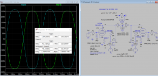
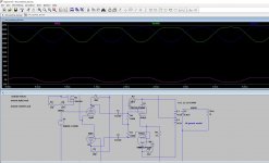
Here is sim of phase splitter stage showing the expected drive level, it should be able to drive the output stage bias @-22V into clipping. Difference in output level is due to the unmatched section of 6gk5. A lot of distortion is due to OT frequency response as you mentioned, making harder to see clearly.
Attachments
Thanks for the advice! 🙂
Are you reading the pins 1&7 for 1.7 off Pointz' schematic?
Oops, yes I was. But still looks a bit low, koonw's simulation and the datasheet curves indicate cathode voltage about 1.1v for 4.7mA each valve. What is the input voltage (rms or peak) when you are clipping the output stage?
I admit that I'm getting frustrated that I'm sure every time I measure this thing, the actual output levels seem different! Might be variances in the USB DAC driving it.
Koonw, thanks for the simulations! I did model it in LTSpice before building it, but I suspect my attempt wasn't anywhere near as thorough as yours. You're clearly better at understanding this stuff than me! 🙂
I'll take a closer look at your sim compared to my setup, but I do notice that on the 'real' amp, the voltages at pins 5 of the 6v6 pair aren't centred around zero, and I get a 47-50v-p2p swing. I presume that's because of the -22ish bias voltage? I'll learn eventually. 🙂
Cheers Tikiroo, I've adjusted this channel for today's tests to 1.19v on the 6gk5 cathodes. Increasing this voltage seems to have the effect of smoothing out the output of the 6gk5 particularly on the 'top' of the sine, seems to have less of an effect on the bottom of the sine wave. I did spot that (though all this testing is on the left channel) I can't get those cathode voltages on the other channel to be above 1.03v or so, as I run out of trimmer. Not sure why the two sides are so different - any ideas on that, or is it normal?
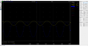
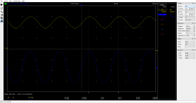
Today's scope traces are at (whatever it feels like this time) today's take on full power. This is driven by the max output of the USB DAC at a measured 2.01v-p2p. Trace attached.
I've attached four traces, at this level, on which the blue trace is the output as measured over the 8ohm load resistor. The HV probe on CH1 is the pin 5 anode outputs of the 6gk5 pair, and the pin 5 'inputs' to the 6v6 (after the cap, and with the bias bled in).
I note that the scope reckons the latter points are at -11/-12vdc bias while running with the signal. Is this correct, or is this an adjustment issue? I can adjust these on the PSU board, but I assumed they relate to the 1v test point as seen at the pin 8 cathodes of the 6v6s? If so, that's sitting at 1.021v today.
I'm still not unhappy with the performance of it, in terms of listening. It'd be nice to learn enough to have confidence in what it's actually doing! 🙂
I've attached my SPICE setup for your amusement / horror. 😉
I really appreciate your attempts to help!
Cheers! PC
Koonw, thanks for the simulations! I did model it in LTSpice before building it, but I suspect my attempt wasn't anywhere near as thorough as yours. You're clearly better at understanding this stuff than me! 🙂
I'll take a closer look at your sim compared to my setup, but I do notice that on the 'real' amp, the voltages at pins 5 of the 6v6 pair aren't centred around zero, and I get a 47-50v-p2p swing. I presume that's because of the -22ish bias voltage? I'll learn eventually. 🙂
Oops, yes I was. But still looks a bit low, koonw's simulation and the datasheet curves indicate cathode voltage about 1.1v for 4.7mA each valve. What is the input voltage (rms or peak) when you are clipping the output stage?
Cheers Tikiroo, I've adjusted this channel for today's tests to 1.19v on the 6gk5 cathodes. Increasing this voltage seems to have the effect of smoothing out the output of the 6gk5 particularly on the 'top' of the sine, seems to have less of an effect on the bottom of the sine wave. I did spot that (though all this testing is on the left channel) I can't get those cathode voltages on the other channel to be above 1.03v or so, as I run out of trimmer. Not sure why the two sides are so different - any ideas on that, or is it normal?
Today's scope traces are at (whatever it feels like this time) today's take on full power. This is driven by the max output of the USB DAC at a measured 2.01v-p2p. Trace attached.
I've attached four traces, at this level, on which the blue trace is the output as measured over the 8ohm load resistor. The HV probe on CH1 is the pin 5 anode outputs of the 6gk5 pair, and the pin 5 'inputs' to the 6v6 (after the cap, and with the bias bled in).
I note that the scope reckons the latter points are at -11/-12vdc bias while running with the signal. Is this correct, or is this an adjustment issue? I can adjust these on the PSU board, but I assumed they relate to the 1v test point as seen at the pin 8 cathodes of the 6v6s? If so, that's sitting at 1.021v today.
I'm still not unhappy with the performance of it, in terms of listening. It'd be nice to learn enough to have confidence in what it's actually doing! 🙂
I've attached my SPICE setup for your amusement / horror. 😉
I really appreciate your attempts to help!
Cheers! PC
Attachments
-
 spice.png44.9 KB · Views: 117
 -
 input_level_off_usb_DAC-219vpp-806vrms.png59.3 KB · Views: 64
 -
 ch1-upper-6v6-pin5_ch2-output-over-8ohm.png69.5 KB · Views: 60
 -
 ch1-upper-6gk5_ch2-output-over-8ohm.png69.9 KB · Views: 69
 -
 ch1-lower-6v6-pin5_ch2-output-over-8ohm.png69.9 KB · Views: 129
 -
 ch1-lower-6gk5_ch2-output-over-8ohm.png70.1 KB · Views: 142
If the input tubes only have about 1V bias, you can not take the standard CD player full scale output (2.1Vrms, 3V peak), or the input stage will clip.
The furthest the input stage grid can move is 1V x 2 = 2V peak (the cathodes are coupled, so the cathodes move at a gain of 1/2 the driven grid voltage).
Use a lower plate resistance, and increase the current through the input tubes; and use an input bias voltage of 2V.
Try and see how that works.
Or, use a balanced signal source, and drive Both input tube grids. The gain will go to 2x of the single grid input circuit, so you get 2X the gain, and 2X more signal before clipping.
You are constrained by the input circuit as it now stands, and by the bias voltage of the output tubes (when their grid signal goes positive voltage that is equal to the grid bias voltage, the output tube grids will clip, and charge the coupling caps, and shift the total bias.
Last edited:
Thanks 6A3, I appreciate the explanation.
Ultimately though, I've got a 100k pot in front of the input stage; surely it doesn't actually matter whether the input stage clips at 1v p2p, or 2v, or any absolute value? In terms of this testing, I mean.
My CD players produce around 6v p2p on the scope (various decent Technics devices), as does my DIY (silicon) phono preamp.
The question started out as 'Is this build doing what the original designer intended', as I wasn't sure. As you say, it looks like it was designed to be driven to max output by 1v p2p on the input, in which case, is the 6gk5 stage doing what it should and providing enough swing on the 6v6 to exercise them sufficiently for the design output? Or is it prematurely clipping before the whole design reaches design output, due to some **** up by myself, moody valves, phase of the moon etc?
Borrowed from the mirror of Pointz' site, and he was talking here about the original variant with the 5965 input stage...
Thanks for the suggestions on the circuit; are you talking about fixing the design limitations here, or making it do what it's supposed to do in the first place? I can live with its limitations if it's functioning as designed. 😎
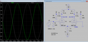
Just playing with this in LTSpice, if I adjust the setting-resistors of the CCS to get 2v on the cathodes of the 6gk5 (4ma cathode current), I can drop the plate resistors to no less than 28k before the anode voltage ends up at the datasheet limit around 200v. Is that what you had in mind? This is without signal - if I add a 2v p2p, we get over 200v peaks on the anode. I've attached a screenshot of this.
Do we think the 6v6 bias is adjusted correctly - i.e. the -23v trimmers, for 1v at the bias test point on the cathodes of the 6v6s?
There's a separate question here of my mini OPTs and their primary impedance. The original design seems keen on high impedance OPTs, up at 10k on the schematic. I'll be the first to admit I understand this bit less than the rest. 🙂 My OPTs are 8k end-to-end primary, configured with a centre tap in use for push-pull. I guess that makes them 2k-CT-2k; what does this mean in practice? I.e. when a 10k primary is recommended in the design, is that 10k end to end, or 10K-CT-10K ?
Cheers!
Ultimately though, I've got a 100k pot in front of the input stage; surely it doesn't actually matter whether the input stage clips at 1v p2p, or 2v, or any absolute value? In terms of this testing, I mean.
My CD players produce around 6v p2p on the scope (various decent Technics devices), as does my DIY (silicon) phono preamp.
The question started out as 'Is this build doing what the original designer intended', as I wasn't sure. As you say, it looks like it was designed to be driven to max output by 1v p2p on the input, in which case, is the 6gk5 stage doing what it should and providing enough swing on the 6v6 to exercise them sufficiently for the design output? Or is it prematurely clipping before the whole design reaches design output, due to some **** up by myself, moody valves, phase of the moon etc?
Borrowed from the mirror of Pointz' site, and he was talking here about the original variant with the 5965 input stage...
... A 6V6 at normal operating point will have a bias voltage of about -20 to -22 volts, so you need about 15Vac for full modulation; and you'd like to fully modulate a line level amp with 1Vac in, for 50% headroom. Loading the 5965's optimally, I'd see a max gain of around 17 or 18 ...
...With a 7.2K load on the outputs, it'll deliver a little over 6 watts at the onset of steady-state clipping...
Thanks for the suggestions on the circuit; are you talking about fixing the design limitations here, or making it do what it's supposed to do in the first place? I can live with its limitations if it's functioning as designed. 😎
Just playing with this in LTSpice, if I adjust the setting-resistors of the CCS to get 2v on the cathodes of the 6gk5 (4ma cathode current), I can drop the plate resistors to no less than 28k before the anode voltage ends up at the datasheet limit around 200v. Is that what you had in mind? This is without signal - if I add a 2v p2p, we get over 200v peaks on the anode. I've attached a screenshot of this.
Do we think the 6v6 bias is adjusted correctly - i.e. the -23v trimmers, for 1v at the bias test point on the cathodes of the 6v6s?
There's a separate question here of my mini OPTs and their primary impedance. The original design seems keen on high impedance OPTs, up at 10k on the schematic. I'll be the first to admit I understand this bit less than the rest. 🙂 My OPTs are 8k end-to-end primary, configured with a centre tap in use for push-pull. I guess that makes them 2k-CT-2k; what does this mean in practice? I.e. when a 10k primary is recommended in the design, is that 10k end to end, or 10K-CT-10K ?
Cheers!
Attachments
I would say it appears that the amp is working as designed.
But I think one of your issues is that you were expecting (wanting) more power from those 6V6 tubes.
Did I understand you correctly?
More power requires some circuit re-design, a lower insertion loss output transformer, or both.
Regardless of the 100k input volume control, the low voltage on the input tube cathodes limits how many volts the input stage can deliver to the 6V6 tubes. And the 6V6 bias voltage limits how much voltage the grids can take before their grids clip.
The output transformer impedances and DCRs, together with the rest of the circuit values, also determine the output power.
Again, no magic here.
I design and build single ended and push pull amplifiers.
Often, I design them for less power out than the output tubes are capable of. But the tubes run cool, and so does the rest of the amplifier.
Just a different set of goals and targets.
Generally, all designs are a compromise of one or more factors.
Have fun listening to what you have.
Then decide if you want to keep the amp the same, or re-design it.
Then build another completely different amplifier as your next project.
Last edited:
Normally i'm a bit of a naysayer (hence my handle), but I think your implementation including the laser → etch business is pretty darn good. Nice job!
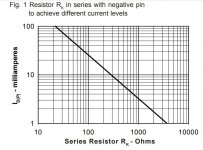
Personally, I would simply double-up the output valves, putting either 2 in parallel at each 6V6 position. Nothing fancy from a current-sharing protocol, just a few 100 Ω plate resistors to even things out.
Your output then goes to about 15 WPC. You will of course have to change the output transformers, but hey… such are the stones one has to forfeit to power. And tho' there are many here who will likely disagree, my sage opinion is that mo' power is betta!
⋅-⋅-⋅ Just saying, ⋅-⋅-⋅
⋅-=≡ GoatGuy ✓ ≡=-⋅
- Home
- Amplifiers
- Tubes / Valves
- 6v6 Musical Machine - Clipping & power expectations