as I said ....... there is no categorization of LEDs primarily by current
they're either "normal" (older) ones , or newer existing - high current range
it's easy to check , with 9V battery and resistor
they're either "normal" (older) ones , or newer existing - high current range
it's easy to check , with 9V battery and resistor
Nice to see that Shindo also use 6V6 in the output of the Vosne Romanee L preamplifier. There is a tube before it, probably capacitor coupled and with parafeed output transformers, but very nice all the same.
The tube before is 6AW8, I think. Parafeed is extremely rare in Japanese gear.
Is their a off the shelf transformer and choke that suits this project or other source for them?
Thanks.
Thanks.
Salas said:skrstic said:Hi Mr. Salas.
I do not know anything about electronics, so I apologize if my questions are stupid.
My parts list is
power
-1 x trafo
340V-0-340V (250mA)
5V (3A)
10V (1A)
10V (1A)
-1 x 5C3S(5Ц3С) tube
-2 x coils 10H
-capacitors
1 x motor-run 4uF
2 x 220uF
I borrowed 2 Russian 6V6 tubes from a friend. Heating is grec-22000uf-lm317.
High voltage looks like:
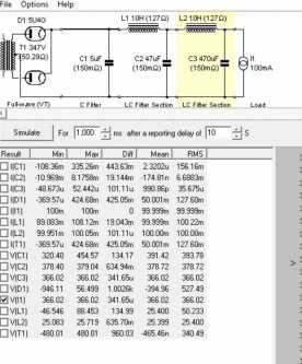
(caps are 220uF)
Questions:
1) I need 1 or 2 SSHV?
2) In PSU Designer load should be resistive or constant current?
3) What value should I put? (constant current 22mA+22mA tubes + 20mA SSHV2 = 64mA)
4) What value R to put on SSHV2 dummy load (340V/0.044mA=7727.27R)?
5) On SSHV2 on TP pads should be 440mV (if 1 is used)?
Thanks in advance. Slobodan.
Hello Slobodan
Please post that questions text to the 6V6 thread so more people can answer or benefit from answers. Since its about things that many others would have questioned too.
From first 45 pages (correct me if I'm not accurate)
1) I need 1 or 2 SSHV?
answer - 1 SSHV2 for regular stereo preamp, 2 x SSHV2 as dual mono or something like.
2) In PSU Designer load should be resistive or constant current?
3) What value should I put? (constant current 22mA+22mA tubes + 20mA SSHV2 = 64mA)
answer - constant current
-65mA four 2 x 6V6 + 1 SSHV2
-42-45mA four mono 1 6V6 + 1 SSHV2
(1 lamp 6V6 is around 22mA depending on manufacturer and 1 SSHV2 is 20mA)
4) What value R to put on SSHV2 dummy load (340V/0.044mA=7727.27R)?
answer - 7k7 for stereo and 17k mono
5) On SSHV2 on TP pads should be 440mV (if 1 is used)?
answer - 440mV for stereo and 220mV
Please double check my answers.
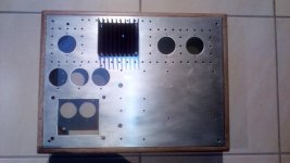
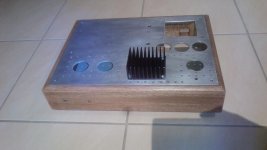
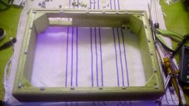
More pics
My friend Skrstic its better to waiting an answer from Nick (Salas).
My friend Skrstic its better to waiting an answer from Nick (Salas).
Attachments
Last edited:
From first 45 pages (correct me if I'm not accurate)
1) I need 1 or 2 SSHV?
answer - 1 SSHV2 for regular stereo preamp, 2 x SSHV2 as dual mono or something like.
2) In PSU Designer load should be resistive or constant current?
3) What value should I put? (constant current 22mA+22mA tubes + 20mA SSHV2 = 64mA)
answer - constant current
-65mA four 2 x 6V6 + 1 SSHV2
-42-45mA four mono 1 6V6 + 1 SSHV2
(1 lamp 6V6 is around 22mA depending on manufacturer and 1 SSHV2 is 20mA)
4) What value R to put on SSHV2 dummy load (340V/0.044mA=7727.27R)?
answer - 7k7 for stereo and 17k mono
5) On SSHV2 on TP pads should be 440mV (if 1 is used)?
answer - 440mV for stereo and 220mV
Please double check my answers.
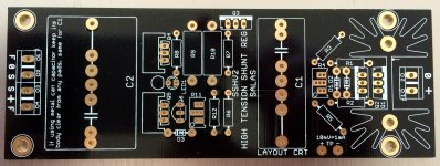
1. One SSHV2 set at circa 60mA CCS can handle two channels. But reconfigure it in two wire mode because the consumption nodes will spread. Two wire mode is short at its output connector legs the F+ and S+ together as well as the F0 and S0 together thus have classic +V 0 two wire output, not Kelvin four wire.
Also use IXYS higher voltage DMOS instead of DN2540 Q1 for more safety since the Vinput is close to the DN's limit in this application. Nikos will kindly remind us the exact IXYS type he put.
2. CC load in the simulator since it remains steady as you change other things
3. Put 60mA because the real tubes usually pull little less than the 22mA per unit prediction
4. Correct. But no need to hit exact mA in this work OK and sinks heat OK preparatory test with dummies. Go with practical dummy resistor values that you can actually find in shops. Go for less mA than more mA when you got to use about values.
5. Should show the total CC current you set. 10mV = 1mA. 600mV for 60mA for example. The newer boards have extra printed directions for quite some time now.
Attachments
Everything uses feedback.
What part of the schematic is the feedback?
Its not the usual loop you see in an amplifier with one resistor coming back from the output and another going to ground, but the small transistors in the regulator react to voltage changes at Vout vs the VRef due to load play and drive the output Mosfet to compensate by adding/removing current to the load, yes? That is feedback. Watching and reacting to a situation. When you write a post in this thread you watch the screen and your fingers run on the keyboard following your thought by your brain overseeing that loop and if they error you delete and replace letters. This is feedback too.
Thanks Mr. Salas.
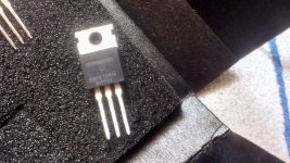
This IXYS IXTP08N100D2?
http://www.diyaudio.com/forums/tubes-valves/102352-6v6-line-preamp-318.html#post5060941
Also use IXYS higher voltage DMOS instead of DN2540 Q1 for more safety since the Vinput is close to the DN's limit in this application. Nikos will kindly remind us the exact IXYS type he put.
This IXYS IXTP08N100D2?
http://www.diyaudio.com/forums/tubes-valves/102352-6v6-line-preamp-318.html#post5060941
🙁 do not have it in farnell or locally. Can IXTP4N80P http://export.farnell.com/ixys-semiconductor/ixtp4n80p/mosfet-n-to-220/dp/1427372?st=IXTP be replacement? Or IXTP8N65X2...
Last edited:
No, the one you linked is a usual enhancement mode MOSFET i.e. it will not be normally on and self bias, needs external bias voltage and its normally off. You look for depletion mode N channel types.
You can alternatively try make SSHV1 on general board though, that uses usual enhancement mode types: http://www.diyaudio.com/forums/powe...stic-mosfet-hv-shunt-regs-97.html#post2084348
If you could find a higher voltage P type for its Q1 (with not too many pF Ciss to avoid slow down much) it would also be safer than the original.
If you could find a higher voltage P type for its Q1 (with not too many pF Ciss to avoid slow down much) it would also be safer than the original.
Its not the usual loop you see in an amplifier with one resistor coming back from the output and another going to ground, but the small transistors in the regulator react to voltage changes at Vout vs the VRef due to load play and drive the output Mosfet to compensate by adding/removing current to the load, yes? That is feedback. Watching and reacting to a situation. When you write a post in this thread you watch the screen and your fingers run on the keyboard following your thought by your brain overseeing that loop and if they error you delete and replace letters. This is feedback too.
Very well explained as always, thank you Salas.
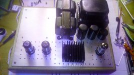
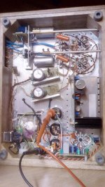
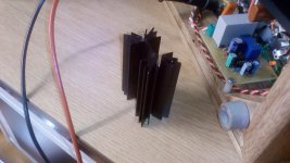
My setup.
640VCT
2X10V /2A for regs 6.3V
5VCT/3A
One reg at 70ma (input 345V-385V) output 330V with IXTP08N100D2
Big heatsing SK129 64mm
640VCT
2X10V /2A for regs 6.3V
5VCT/3A
One reg at 70ma (input 345V-385V) output 330V with IXTP08N100D2
Big heatsing SK129 64mm
Attachments
Last edited:
- Home
- Amplifiers
- Tubes / Valves
- 6V6 line preamp