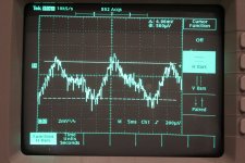
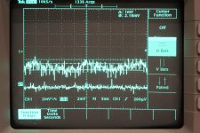
Here is cursors. The curves are very probe-positioning dependent tho. We are down to so low levels that everything interferes, even my hands.
I think I have an OK B+ tho. Well last 220 caps are maybe not state of art but they work and theyre sturdy for experimental work. Ran one backwards on 350 V yesterday and it didnt mind. Have hundreds of them.
Wopsie. This is actually 340 v B+ with 1x probe. Poor scope😱
Hehe, to many open questions now😀
Please tell me what to do and I'm your slave after getting the probies😉
Please tell me what to do and I'm your slave after getting the probies😉
If it was a vivid signal with lots of HF the probe gets it first. On the bright side, you got your best SNR of the interface for a brief.😀
As I see its a stable circuit and all you got to do is put it together for the least 50HZ and 100HZ (I mostly saw 10mS), for when using 1X probe, BW limit, 2mV/div with the tightest probing to ground method from its audio output. Keep the loop areas tight everywhere for the least uncertainties in your way.
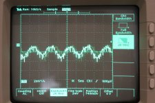
About AC filament hum its not clear because I don't see a 20mS cycle but a 10mS dominant cycle. 10mS=100Hz so it must be the amplified ripple for most. The dirty things can be the filaments need DC and ground idea is to be explored. Can be mains dirt, can be 100Hz harmonics, can be the probing.
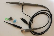
Super. Went to the post office to get the probes, also carrying a bag of return cans. Arrived without the slip and the can-machine was broken. Two jokers in one pull. Anyways, got some unwanted exersice so now I'm back with 2 hong kong probes. They dont seem to come with anything but the alligator. Shall I try a homemade groundclip?
About the 100 Hz I can try starground last 220 uFs, those now audioground as can be seen, and also bypass them with some quicker stuff.
About the 100 Hz I can try starground last 220 uFs, those now audioground as can be seen, and also bypass them with some quicker stuff.
Attachments
Tried a homemade groundclip. Luckily I was not able to photograph and hold it in the same time cause the curves looked like ****.
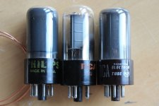
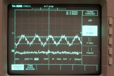
Then I did some tube rolling for fun. First Philips you have seen so I followed up with two different RCA types. Quite different as you see. Im betting on the filaments.
Then I did some tube rolling for fun. First Philips you have seen so I followed up with two different RCA types. Quite different as you see. Im betting on the filaments.
Attachments
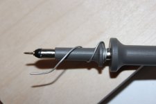
You made a long coil. Make a shorter one from tip ground distance not from its back.
Quite different the screens indeed and 20mS in period now. That is hum now. 1/20ms=50Hz
Quite different the screens indeed and 20mS in period now. That is hum now. 1/20ms=50Hz
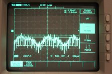
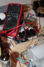
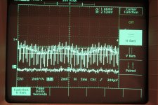
This is fun. Basic research for me. So I made a rectify and passive filtering of the 6,3 V I had at hand. Pic 1
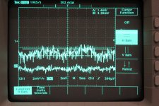
Pic 2 is the new curve of the ashy RCA black anodes that made the worst result before with AC. Channel 2 is the rectified filaments. Interesting?
Pic 2 is the new curve of the ashy RCA black anodes that made the worst result before with AC. Channel 2 is the rectified filaments. Interesting?
Attachments
Last edited:
I cant stop blabbering. Look at tube differences. They eat around the same starved voltages with rectified and smoothed 6,3 v (around 5,8 V) wich they absolutely dont when CSS feeded. Then they vary around 1 V. And those are the differences on 3 tubes. 1 Ashy RCA, 2 Clear RCA, 3 Ashy Philips. Note those are DC lifted to 58 V at their usual ground (zero)
Attachments
Last edited:
Stajo - Great information! Keep it coming!!
What are you measuring in the above photos? I can't figure it out... What are you looking at on Chanel 1, and what is channel 2?
What are you measuring in the above photos? I can't figure it out... What are you looking at on Chanel 1, and what is channel 2?
Stajo - Great information! Keep it coming!!?
Thanks! Im famous for rolling OT but this is not so much about building a great amp for me at the moment. Its more about investigating what affects what and learn to measure it with the tools I have at hand. Glad you enjoy.
What are you measuring in the above photos? I can't figure it out... What are you looking at on Chanel 1, and what is channel 2?
Channel 1 is output from one channel on the current build (6V6 AF) after cap measured with 1x probe on max sensitivity on my scope, 2 mV/div. So we are talking high SNR here even so.
Channel 2 is filaments on different 6V6es. All from AC to DC.
So next task is to CSS reg the filaments, but then I need to voltdouble the 6,3 V AC and rig a LM CSS. Gonna take time. Either that or some beers at the pub. What do you think?
Channel 1 is output from one channel on the current build (6V6 AF) after cap measured with 1x probe on max sensitivity on my scope, 2 mV/div. So we are talking high SNR here even so.
Channel 2 is filaments on different 6V6es. All from AC to DC.
Ok, that is making more sense. Thanks!
So Channel 1 is the noise on the output?
Is the input shorted or open?
And channel 2 is filament noise?
G1 has a 68k fixed to ground atm.
Ch 1 is noice at output yes, probably mixed with noicy environment but its the differences that is interesting, not the exact measurements.
Channel 2 is half-poor rectified filaments, made from what I had handy.
1x probe on both and 2 mV/div
Ch 1 is noice at output yes, probably mixed with noicy environment but its the differences that is interesting, not the exact measurements.
Channel 2 is half-poor rectified filaments, made from what I had handy.
1x probe on both and 2 mV/div
Ch 1 is noice at output yes, probably mixed with noicy environment but its the differences that is interesting, not the exact measurements.
The differences are very interesting - I knew that the changes were due to the different tubes, and that's why I wanted clarification on what you were measuring.
Nice 'scope, by the way... 🙂
- Home
- Amplifiers
- Tubes / Valves
- 6V6 line preamp