Hi,Hey Salas, do you still like the Maida regulator PSU for these? I'm currently working on PCBs for power supplies and was thinking of putting one together as a spiritual companion to the other boards.
I'm also putting together a simple mosfet ripple filter PSU on a 50x50mm PCB as well since it's what I use in 75% of my own builds, same basic circuit as the one Pete Millet used in his Engineer's Amplifier, but just with a diode bridge-
It would be easy to start with this and expand it to 50x100mm to work in an LM317T to make a Maida regulator board.
Maida measures cleaner FFT grass with more PSRR, cap multiplier has 10dB more hum as it ups output impedance towards the lows. For directly felt noise they are both sufficient. Filter sounds rounder, Maida more neutral. I like both depending on system synergy.

Hmmm.
Sy's Red Light Distrct amplifier turned me on to the Maida and it worked great for me on the screen supplies for pentode amplifiers. Haven't built one in years due to complexity and messy protobJones. The use of an LM317 IC may cause some folks to turn away, however.
The Engineer's amplifier turned me on to the mosfet filter, and I use it for most of my builds now. I really like it for screen supplies and lower power class A stuff. Dead silent and simple.
I've also used shunt regulators in the past and was happy with them- VR tubes fed by CCS being my favorite so far. There's also the zener types such as the Statistical Regulator by Morgan Jones.
I suppose for what we are doing here they all will work very well, just depends in how complex people want to go.
How many power for Rset 10W?
I ask because I'm sure I have a reactor of 5W but not sure of 10W.
I ask because I'm sure I have a reactor of 5W but not sure of 10W.
Last edited:
For the LM317 set up as a current regulator- the formula is easy. 1.25 volts divided by the resistor value in ohms will give you the current, this current multiplied by the 1.25 volts will give you the resistor dissipation in watts- you then derate the total wattage in order to keep the resistor from running too hot, a common and smart practice is to make the actual resistor wattage 2-3 times higher than needed.
For example, assuming a 2R7 resistor, 1.25/2.7= 0.462. This multiplied by the 1.25 volts is 0.578 watts. So I would use at the very least a 1 watt resistor, but it would be screaming hot. Better yet a 2 or 3 watt so that it will not run too warm. 5 or 10 watt would be lovely.
For example, assuming a 2R7 resistor, 1.25/2.7= 0.462. This multiplied by the 1.25 volts is 0.578 watts. So I would use at the very least a 1 watt resistor, but it would be screaming hot. Better yet a 2 or 3 watt so that it will not run too warm. 5 or 10 watt would be lovely.
Last edited:
Thanks Lingwendil, I know and made the maths so the reason I asked.
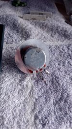
Salas got the rheostat 3R 5W that kindly sent me time ago and never used.
Salas got the rheostat 3R 5W that kindly sent me time ago and never used.
Attachments
Last edited:
If you use that and a 2R2 in series you should be good to dial in whatever you need.
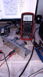
Across the setting resistor(s) there must be about 1.25V for LM317.More than 1 minute warm up. Resistor + rheostat set to max. 6R11. Across res+pot measures 2.7V = 442mA it seems not enough.
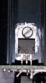
7.56V at filaments & 1.72V across 3R3 = 521mATry 3.3Ω resistor alone (between adj-out pins)
Last edited:
1.72V is way out of LM317 Vref spec and tolerance. It either gets too hot or its a fake sample. Is it on a sink?
Replace it. Vref in a reg chip is an essential function. Must be close to nominal and steady. Can't be far away from 1.25V or changing with different resistors.
When you measure directly on adj and output pins what gives? If around 1.25V the chip is good so review the connection points of the experiment for error.

- Home
- Amplifiers
- Tubes / Valves
- 6V6 line preamp