Good progress. Still to clean the B+ and isolate better mechanically as you say. Also check if the hum is 50Hz drone or 100 Hz deep buzz and rough harmonics. Pure hum can be ground loop also.
Yes, is what I've in mind, also I' ll control for ground loop but i've wired the circuit with a star ground so what i've to verify probably is the shield of the cable of input and output line that i've connected only from one side to the ground (typically the second side) but Always togheter for the two channel (is right?).
Again I have a question, for the AC heater I connect one wire to the ground, so the filament is about 127 V under cathode, maybe raising the point of AC to 100V could reduce HUM? a resistive partitor with a condenser could be useful ? if yes and don't want to loose too much current how big could be the sum of the two resistor?
The Hum is probably on 50Hz ...I don't have tools to verify but my hear was as good enough to appreciate the difference, is not high level but is like "rumble noise", and I have a solid state AMP and 93db loudspeaker that replicate it perfectly, while with an EL34 AMP those was practically not audible. for this my suspects are on mechanical vibration.
Thanks for any help
As I understand it, higher GM tubes lead ultimately to lower output impedance. While as low as possible is attractive, I figure the 6v6 would be around 600ohms. If this is incorrect, how do I go about figuring the Zo?
1/gm
Yes, is what I've in mind, also I' ll control for ground loop but i've wired the circuit with a star ground so what i've to verify probably is the shield of the cable of input and output line that i've connected only from one side to the ground (typically the second side) but Always togheter for the two channel (is right?).
Again I have a question, for the AC heater I connect one wire to the ground, so the filament is about 127 V under cathode, maybe raising the point of AC to 100V could reduce HUM? a resistive partitor with a condenser could be useful ? if yes and don't want to loose too much current how big could be the sum of the two resistor?
The Hum is probably on 50Hz ...I don't have tools to verify but my hear was as good enough to appreciate the difference, is not high level but is like "rumble noise", and I have a solid state AMP and 93db loudspeaker that replicate it perfectly, while with an EL34 AMP those was practically not audible. for this my suspects are on mechanical vibration.
Thanks for any help
Since you said there was no real difference in hum with DC heating maybe you have not to expect solving this by floating the AC heating but you must always lift it if its more than the tube spec heater to cathode max so to save material wear. High voltage difference is happening in the buffer version. The lifting resistors can be in the several hundreds of kOhm.
50 Hz (and not 100) hum has its source in non- or pre regulated AC in 50 Hz countries so you shall look for either ground loop hum which is the most usual or an AC lead in, trafo or something there that inducts the signal now when you have excluded filaments. 100/120 hz is usually rail related like bad filtering.
Yesterday i lift them to about 90v with resistor avalaible, the hum still remain as salas said I have veryfied every link to ground and finally discovered a possible Source in vibration of transformer so next week my work will to mechanical side to reduce vibration and also give a lr8 based ripple reduction on B+ rail.
It is vert fun as built a musical instrument.....
It is vert fun as built a musical instrument.....
Yea the 6V6 is relatively microphonic at those levels so it might be well worth to isolate vibrations.
The problem of HUm was solved, I rewire everything with careful to grounds and position of components, also I balance the AC but what was definitive was to change gyrator with a simple inductance , the pre happen silent more than solid state AMP I use with.
Also I change to gain configuration schematic to listen differences, it is beautiful but a serious comparation wasn't possible becouse I pay for inductance use about 40V on B+ so I'm thinking a good way to raise B+ with components on my hands, probably the doubler is too much but a series of High voltage capacitors in parallel to diodes could be useful? there is a better way? the actual transformer coud give 230 V with 180 mA
Also I change to gain configuration schematic to listen differences, it is beautiful but a serious comparation wasn't possible becouse I pay for inductance use about 40V on B+ so I'm thinking a good way to raise B+ with components on my hands, probably the doubler is too much but a series of High voltage capacitors in parallel to diodes could be useful? there is a better way? the actual transformer coud give 230 V with 180 mA
The problem of HUm was solved, I rewire everything with careful to grounds and position of components, also I balance the AC but what was definitive was to change gyrator with a simple inductance , the pre happen silent more than solid state AMP I use with.
Also I change to gain configuration schematic to listen differences, it is beautiful but a serious comparation wasn't possible becouse I pay for inductance use about 40V on B+ so I'm thinking a good way to raise B+ with components on my hands, probably the doubler is too much but a series of High voltage capacitors in parallel to diodes could be useful? there is a better way? the actual transformer coud give 230 V with 180 mA
Good. Do you use tube or silicon for rectifying?
Actually silicon, with simple diodes, I'm thinking to use ultra fast UF or a 5U4G in my hand but as you can see the actual cabinet is very little and I like his minimal style..
Ok, so no voltages to mention to get there. Maybe a voltage doubler and tube rectifying would get you in the game.
The problem of HUm was solved, I rewire everything with careful to grounds and position of components, also I balance the AC but what was definitive was to change gyrator with a simple inductance , the pre happen silent more than solid state AMP I use with.
Also I change to gain configuration schematic to listen differences, it is beautiful but a serious comparation wasn't possible becouse I pay for inductance use about 40V on B+ so I'm thinking a good way to raise B+ with components on my hands, probably the doubler is too much but a series of High voltage capacitors in parallel to diodes could be useful? there is a better way? the actual transformer coud give 230 V with 180 mA
Nice one with the hum solving

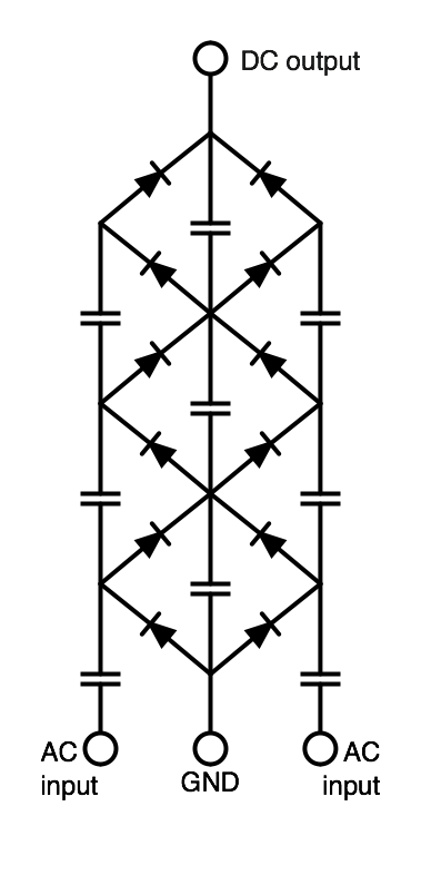
The Cockcroft-Walton cascade you thought of, if I got you right as in the picture, VS simply voltage doubler of any type is a way to go x4 x6 x8 etc. Not what you look for.
230 V on secondarys would give you some 320 on the first cap. Then you could filter 20 and give an SSHV 20 for overhead. That would give you 280 V on the anode on a cathode follower. Would work. Or what have I missed?
Another approach is to accept it sounds good anyway in this lowered Vp/Ip operating point too, plus no hum anymore, and call it a day 😀
230 V on secondarys would give you some 320 on the first cap. Then you could filter 20 and give an SSHV 20 for overhead. That would give you 280 V on the anode on a cathode follower. Would work. Or what have I missed?
You missed none, after CLC plus bleeder resistor of 330K I've 280, after there are two resistor (50R) with big capacitor for each channel at about 270 and it run, what I would try is to raise more volt as possible to B+ becouse I loved the sound on 310 volts but the hum was audible.Again as I say before, this is my game : give out the best sound with the actual constraints (box, components avalaible, ecc)
What I have reached last evening is enough and I could use it as Salas says (and I use it listening music last night) but...why stop this game?
what you think about?
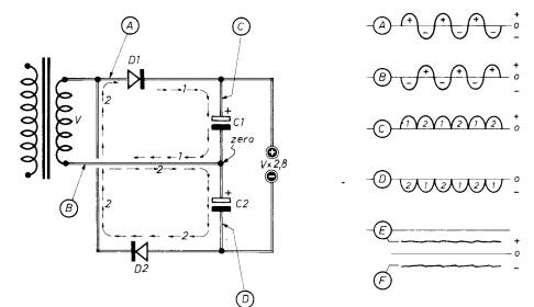
I think thats a voltage doubler. And your doing the right thing to experiment. Tho I dont think you will find anything better up there in the voltages linearity wise. But linearity is not everything. Experimenting is tho. Keep on.
Two keys to a good tube based CF tho. High transconductance tubes and a stiff under lip. Try sim a CCS in the bottom instead of a resistor that steals your voltages. Or a proper inductor. Will save you voltages and give you the oomf. An active CSS is about the same as a large inductor and as a very large cathode resistor. Just that your resistor has to be in the Mohm class to compare and THAT would steal some voltages.
Last edited:
- Home
- Amplifiers
- Tubes / Valves
- 6V6 line preamp