does tuning effect port area itself? that is to say if you have a box tuned at 30 and another tuned at 50, would you expect one frequency to require more area of port vs the other?
how long is too long on a port? if a port 1st resonance is more than double your xover frequency is that all you need or is there a 'number' on the maximum desired length of a slot port?
i have read that a 6th order wants chamber A to be 1/2 the size of chamber B. is this a hard rule OR can it be more like chamber A is +/- [%] of chamber B?
what is the difference between a parallel and a series 6th order? why choose one over the other and what programs can model (or what is the math) to compute a series'd port?
6th order have so many variations and is complex to build. You should use WINISD for learning and build some test enclosures.
i have winisd and termlab pro. if i go off these programs, making both chambers roughly the same size would net me the most output, however i have read that doing this will induce cancellation due to phase inversions at the ports. this is hwy i am asking for answers to non specific questions regarding the fundamentals.
Is this enclosure supposed to be for sound quality or is it a one-note enclosure for some sort of competition?
not pure SQ by any means but i want it as loud as i can get across as many frequencies as i can manage. as such i have been looking at a 25/55 (ish) htz tune. in winisd the 6th can span FAR more frequencies than the standard ported does and at roughly the same volume peak to peak
Typically, if an enclosure like the 6th order is tuned to a narrow band (the only way the output can be significantly more than a sealed or ported enclosure), the system becomes known as a one-note wonder.
Have you tried to use a sealed or standard ported enclosure and they were insufficient?
Have you tried to use a sealed or standard ported enclosure and they were insufficient?
A few comments from my not inconsiderable experience in designing and building literally dozens of these in the 90s.
1) If the air in the port begins moving somewhere near 1/2 the speed of sound, you start getting port noise; this has to do with air pressure, port and moving air volume and the related surface area of the port. Speaker dia, xmax obviously play a part in this, as do sharp edges and restrictions. The closest description a car guy would be familiar with is the cylinder head and intake manifold port flows; bigger isn't always better, depending on speed and rpm.........lots of parallels.
2) Certain speakers function much better within various environments. In my experience, lots of subs that work well in sealed enclosures can work well in 4th order boxes. Same with subs that like ported enclosures can sometimes really like the double vented 6th order design.
3) Making a 6th order relatively sound Q will not necessarily give you significant boost across a wide frequency range; but it may.
4) Usually, for a 6th order to be efficient and decent sounding, it's gonna be massive in size. Add in the large port areas, keeping the port origin far away from walls and floor of the enclosure, and you have something that is not going to be very space efficient, if even possible to install into a car or the space you have in mind.
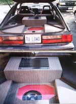
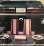
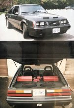
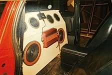
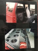
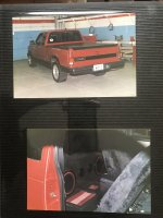
A good bandpass enclosure can be a revelation when considering the limited cone area vs output - one of the best sounding bandpass I ever built was a Pioneer TSW201C 8" in a 6th order, overpowered by a GMH200 in mono. It sounded really nice and tight, had excellent low end extension....but wasn't loud enough despite going above 120 dB in the Fox Mustang hatch. I also built a Chevy Lumina demo car for Pioneer using two of their sealed 10" in two 4th order enclosures, with external tube ports running into the rear seat. That was also quite impressive sounding and was over 130dB with relatively modest 160W rms per speaker. Still, way too big compared to a good sealed or even free air or ported desgin; but........it showed what is possible. Pls see the attached pics. Also, in my experience, bandpass enclosures typically require some real mid bass support from ideally 2 or 4 eight inch woofers in order to add the midbass precision that will be missing.
1) If the air in the port begins moving somewhere near 1/2 the speed of sound, you start getting port noise; this has to do with air pressure, port and moving air volume and the related surface area of the port. Speaker dia, xmax obviously play a part in this, as do sharp edges and restrictions. The closest description a car guy would be familiar with is the cylinder head and intake manifold port flows; bigger isn't always better, depending on speed and rpm.........lots of parallels.
2) Certain speakers function much better within various environments. In my experience, lots of subs that work well in sealed enclosures can work well in 4th order boxes. Same with subs that like ported enclosures can sometimes really like the double vented 6th order design.
3) Making a 6th order relatively sound Q will not necessarily give you significant boost across a wide frequency range; but it may.
4) Usually, for a 6th order to be efficient and decent sounding, it's gonna be massive in size. Add in the large port areas, keeping the port origin far away from walls and floor of the enclosure, and you have something that is not going to be very space efficient, if even possible to install into a car or the space you have in mind.
A good bandpass enclosure can be a revelation when considering the limited cone area vs output - one of the best sounding bandpass I ever built was a Pioneer TSW201C 8" in a 6th order, overpowered by a GMH200 in mono. It sounded really nice and tight, had excellent low end extension....but wasn't loud enough despite going above 120 dB in the Fox Mustang hatch. I also built a Chevy Lumina demo car for Pioneer using two of their sealed 10" in two 4th order enclosures, with external tube ports running into the rear seat. That was also quite impressive sounding and was over 130dB with relatively modest 160W rms per speaker. Still, way too big compared to a good sealed or even free air or ported desgin; but........it showed what is possible. Pls see the attached pics. Also, in my experience, bandpass enclosures typically require some real mid bass support from ideally 2 or 4 eight inch woofers in order to add the midbass precision that will be missing.
Attachments
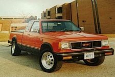
and the Mustang; this car had about 10 competition level systems in it, most of them never fully trimmed and finished. 2 15s and 4 eights, 4 tens in two totally different arrangements; single 12, single 8, 4 12s isobaric sealed etc etc......23 years of one car ownership allows for some variety, lol
Attachments

Yes!
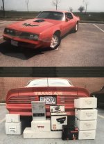
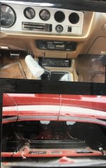
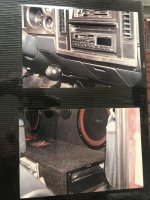
The shaft-mount Concord and early Sony CD give us a pretty good date on this one, and it wasn't 90's! I don't want to stray from topic, but are those Becker woofers in that pic?
The shaft-mount Concord and early Sony CD give us a pretty good date on this one, and it wasn't 90's! I don't want to stray from topic, but are those Becker woofers in that pic?
thanks for some info, its very, very hard to find anyone who has real experience with these more complicated boxes.
i have noticed space is an issue, i have a fair amount to play with so lets set that aside. in my modeling i see about 25m/s air speed. now i had assumed the lower tuned port would need to be larger than the higher tuned in order to keep the mach factor down. however this seems to not be the case and is sort of counter intuetive for me.
when i look at my ported box it peaks around 35hz and drops off pretty steeply. the 6th order seems to be more flat from 30-60hz. the dip is only a bit quieter than the peak of the ported and i figure i can do some eq to lower the peaks and flatten things a bit if needed. i also see some phase issues between the ports when using two chambers that are about hte same size. i 'think' i could run an allpass filter to change htat but im not sure.
winisd shows two large chambers has more output on paper than a large and a small but will that transfer to the real world? also you mentioned the ports being away from the enclosure walls. i had planned on two ports, one on left side nad one on rihgt side - facing up. is that ideal? i hadnt thought about port orientation.
i am thinking of kerfing the inner ports to make a continuous bending port with out any abbrupt changes in angle.
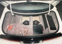
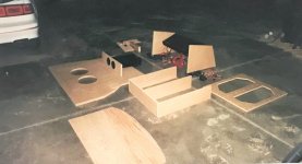
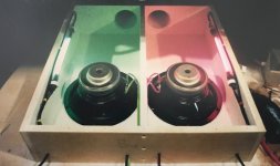
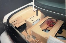
here is my rough draft:
i have up to 30 cubic feet to play with and still retain my rear window. if i go into the rear window i have 67 cubic feet but i really dont plan to use all that.
i have noticed space is an issue, i have a fair amount to play with so lets set that aside. in my modeling i see about 25m/s air speed. now i had assumed the lower tuned port would need to be larger than the higher tuned in order to keep the mach factor down. however this seems to not be the case and is sort of counter intuetive for me.
when i look at my ported box it peaks around 35hz and drops off pretty steeply. the 6th order seems to be more flat from 30-60hz. the dip is only a bit quieter than the peak of the ported and i figure i can do some eq to lower the peaks and flatten things a bit if needed. i also see some phase issues between the ports when using two chambers that are about hte same size. i 'think' i could run an allpass filter to change htat but im not sure.
winisd shows two large chambers has more output on paper than a large and a small but will that transfer to the real world? also you mentioned the ports being away from the enclosure walls. i had planned on two ports, one on left side nad one on rihgt side - facing up. is that ideal? i hadnt thought about port orientation.
i am thinking of kerfing the inner ports to make a continuous bending port with out any abbrupt changes in angle.
here is my rough draft:
i have up to 30 cubic feet to play with and still retain my rear window. if i go into the rear window i have 67 cubic feet but i really dont plan to use all that.
Last edited:
as for wattage, does the 6th order change how much power the sub can handle? such as ib can take far less power and sealed can take more than a vented? i plan to have about 3500W@2ohm for mono block
The 6th order (or even 4th order) can mask stress (from the speaker being over-driven) that you would hear in other types of enclosures.
Good eyes - yes - the Beckers were pretty awesome for the money back in the mid -late 80s. My 77 Trans Am had 4 of them free air on an Orion GX2200 at 2 Ohm stereo....was real loud and tight, especially for way back then......
The inside dimensions of the enclosure need to avoid being cubic or having 2 identical measurements in the interest of reducing any standing waves or resonance.
A good 6th order design pulls the two peaks together to basically create one flat shelf with a bunch of boost, but at least flat across half an octave, if possible. Sometimes it's easy and sometimes it ain't - depends on the speaker reaction to the design.
Another issue is the internal maximum wavelength your Van? cause no car has that much air volume, lol
The rate of roll off is also of concern - as a 6th order is very steep below the lower resonant frequency. At some point, a sealed box will have higher output, albeit way low in the frequency range.
The maximum internal vehicle dimension, in relation to a quarter wavelength calculation would also not be a bad number to figure out, since that will be (theroretically anyway) the lowest note the vehicle will contain. 1/4 wave is the first peak, which is really what you are after.
Here are a couple of designs I published for Pioneer and Dr. Crankenstein back in the mid 90s when I worked for them both.
Attachments
im going to do some research around what you said here and get back to you. im just getting into this level of design. i work at an audio shop and had an orca training last year on their aerospace DSP that talked about computing waves to set staging. ill need to go back over my notes from then.
its a truck (4 door), not a van. rear seat is pulled. i could angle one chamber wall to change its dementions across the board. also mounting the sub inside - off center - will help. having one smaller chamber will also go a way to helping with that.
as for chamber sizes, does the 50% smaller rule hold true? if one chamber is 8 cubic i wont want the 2nd to be any more than 4 OR do i just need to make sure it cant have any cascading or coupling standing waves with the other chamber?
also if the ports 1st resonance is at minimum 1 oactive more than my Xover point on a 12db slope, is that good enough or do i need a steeper slope OR a higher resonance?
now what do you mean by bringing the peaks together? tuning the two closer so there is less gap between or?
also the 2nd line on the graph (if you didnt guess) is that sub in a vented box, the box i currently have.
that;s a lot of questions I cannot answer other than pulling the peaks together to get a single flat output curve. This will be done via the port resonant frequencies and box volumes, which is why it's nice to have a computer system to calculate these. I do not have any software, so I am not able to comment directly.
Power handling is vastly increased practically speaking when including xmax and cone folding etc.......however; the ultimate ability for the voice coils to dissipate maximum heat is going to be a mystery of sorts, since the specs are likely based on sine wave power handling, not transients and music. Perry is correct in that these enclosures will mask some of the mechanical at the limit noises, but a proper design will increase the power handling over a conventional sealed or ported enclosure. I will try to dig up some 4th and 6th order designs from my past and post them later.
Power handling is vastly increased practically speaking when including xmax and cone folding etc.......however; the ultimate ability for the voice coils to dissipate maximum heat is going to be a mystery of sorts, since the specs are likely based on sine wave power handling, not transients and music. Perry is correct in that these enclosures will mask some of the mechanical at the limit noises, but a proper design will increase the power handling over a conventional sealed or ported enclosure. I will try to dig up some 4th and 6th order designs from my past and post them later.
- Status
- Not open for further replies.
- Home
- General Interest
- Car Audio
- 6th order box design