First find out what flavour of hum it is, IE 50/60hz or 100/120hz. Have you a scope?Any suggestions on how I can get rid of the hum
First scope V1 g1, what do you see? Also check ripple on your power supply using a scope or DMM, carefull with using a scope, make sure you're not exceeding your scopes IP V max, you can always tack on a 0.01u or 0.1u 630v rated cap to the reservoir cap if needed.
Check your grounding scheme and check and recheck your work in case you've made any booboo's like connecting a cap the wrong way round or using a 100k R instead or a 100r R,that sort of thing.
Andy.
I figured out the problem. after the B+ voltage out from the bridge recitifier and filtering capacitor, I have a voltage dropping resistor. I added a second capacitor after the voltage dropping resistor and the hum completely disappeared.
Good news. Did you use 1/(6.28 * f * r) to find the right cap value? f =frequency, r = resistor value. Use 1 for f or leave f out.
Andy.
Andy.
Good news. Did you use 1/(6.28 * f * r) to find the right cap value?
----------------------------------------
How so?? Larger RC product simply results in more attenuation of the hum. There is no 'right' cap value.😀
----------------------------------------
How so?? Larger RC product simply results in more attenuation of the hum. There is no 'right' cap value.😀
Ehhhh? If you just bung a 1m resistor and 1F cap 450v at the job it will reduce hum but will reduce HT and £'s/$'s in ones pockets. Why sod about when you can figure out the optimum component values for a filter?How so?? Larger RC product simply results in more attenuation of the hum. There is no 'right' cap value
Andy.
Steventrus said the R was already in place. More C to common = more attenuation of the hum.🙂
This thread sounds much like Rhythmsandy again. Or perhaps a clone.That staggered about for a long time & eventually crashed & burned.😀
This thread sounds much like Rhythmsandy again. Or perhaps a clone.That staggered about for a long time & eventually crashed & burned.😀
I have tried the following way with CF as well but the same hum residue is there. Which is 100Hz.
I have used the following elevated the heater rails to 60VDC with 220k resistor and 50k resistor and using 100uf cap decoupled to the elevated heater point.
Tried DC heater with 10000uF the hum reduced signficantly but its there.
applied artificial center tap for heater with two x 220ohm resistors and connected that to power ground and also tried with signal ground. Nothing the hum is still there.
Tried chassis wire to B+ gnd and tried both the ways with 10ohm resistor || with 100nF with 35Amp diode bridge.
The hum is still there
I built a preamp, similar to the circuit you provided, but with 12AH7.
The PSU uses a primary transformer with 2x18V secondaries, one for the heater PS, the other feeding another transformer back to back, secondary to secondary and then RCRC followed by a CapMX with a FET. That provides around 250VDC.
The heater PS is also heavily filtered and followed by a 12V IC regulator with couple of diodes to bring the voltage to 12.6V. The heater is elevated of course.
There is no hum, no noise whatsoever. Everything is assembled on proto boards.
Also built a SRPP head amp with an added secondary to the main transformer for the heater PS. The B+ uses a voltage doubler, plus RCRC, plus CapMx again with a FET. Also assembled on proto boards.
And again no hum, no noise, etc.
So it can be done.
I don't have sufficient knowledge of electronics theory to figure out values of capacitors. So what I did was base my numbers on other applications. I have a DIY vacuum tube amp that I built that used a 330UF capacitor after rectification and so I used that value. Then I need a voltage dropping resistor. Since I didn't know the current flow, I could not figure that out using Ohms law, so i did this by trial and error. I started with a 10K resistor and experimented until I found that a 2.5k resistor dropped the voltage to the correct amount (220v) for the morgan jones headphone amp. But that had a terrible hum and so looking back at my DIY tube amp, I realized that i needed a second filtering cap after the voltage drop resistor. So I just guessed and used the same value (330UF) and it worked perfectly. The hum is completely gone. The version I used is the one with three 6n11 (=6922) tubes. Previously I had build a solid state headphone amp based on the lehmann circuit. It sounded quite good, but the morgan jones one is significantly better sounding in my opinion. I highly recommend this design if anyone is interested in headphone amps.

6N11P sounds very different from 6922 although they have the same pinout and device won't be damaged with either tube.
I used the 6n11 which is almost identical to 6922. You may be thinking of the 6n1p, which is as you said very different than the 6n11
Yes, i had 6N1P in mind, thanks for correcting me. Looked at 6N11 and Telefunken or Tesla 6922 datasheets and found a lot more variance even in military grade 6N11.
It would be interesting to see how matched are 6N11 out of factory, then measure distortion and other parameters at the same conditions for both tubes. I never tested or heard 6N11 myself.
It would be interesting to see how matched are 6N11 out of factory, then measure distortion and other parameters at the same conditions for both tubes. I never tested or heard 6N11 myself.
Good point about tube rolling. I just finished building this amp over the weekend and have only tried it with the tubes that i purchased for it, which are a Chinese brand referred to as "Beijing 6n1" I don't have any 6922s yet - i will purchase some to do a comparison. In my opinion this amp sounds fantastic and is way better than the solid state one i built based on the lehmann design.
The amp i built is from the following link:
The Morgan Jones Mini Tube Headphone Amplifier. – HeadWize Memorial
I built the second one called the "optimized Morgan Jones Amp" The main difference between it and the original one is that the output electrolytic capacitor is 470uf versus 220 uf in the original. It doesn't explain why the change in the article. Does anyone know about this change?
Higher value output coupling cap allows it to pass lower frequencies. Different biasing might be more noticeable, didn't calculate lowest freq of each preamp to tell if that is so. Having matched tubes will also help.
6N1P has very different distortion from E88CC (at the same bias and used as grounded cathode), i only found 1 pro audio application (this is what i like to diy) where 6N1P sounds better. Maybe others measured this difference, it is quite big and would be interesting to know why.
6N1P has very different distortion from E88CC (at the same bias and used as grounded cathode), i only found 1 pro audio application (this is what i like to diy) where 6N1P sounds better. Maybe others measured this difference, it is quite big and would be interesting to know why.
working on my second build. What if we change the cathode bypass capacitor in Mu follower to 1000uF unable to control the ground loops no matter what. Tried Toroidal transformer and also R core where R core is slightly better but when my hand goes near to the tube it starts humming even more.
OK if you think its getting in on the HT, split R3 say 47K to plate and 10K to supply. Then add say 22uF 400V to ground on junction. If its more of a buzz this can be the heater supply coupling into the first grid or cathode. Making sure your heater is balanced, keeping it away from the grid, bypass cathode resistor (will change gain) or DC heater helps. Keep any rectifier return currents out of signal ground.
converted to DC heaters at 6V like what Audionote does and the hum is gone there are pros and cons. Firstly slightly the bloom is reduced secondly the inner detail seems increased and the separations have better distinction now. Infact I liked it. The DC for the psu is simple Bridge and alot of capacitance to even out. I know there will be slight ripple but the actual hum is gone and also that little ripple might be just like small AC to the heater. Since the problem is solved im quiet happy but might be looking for a regulator in my next build with Tube rectifier 5AR4 with double C core chokes and transformer coupled output.
I have some ultra low frequency oscillations sometimes I see the speaker cone is softly displacing.
I have some ultra low frequency oscillations sometimes I see the speaker cone is softly displacing.
figured out the reason why the ultra low freq oscillation was happening because of LC resonance so tweaked it for better stability.
If I have to connect a output transformer with 10k input impedance in the Mu follower then where to connect?
Last edited:
what is this Fitz mod?
https://www.head-fi.org/threads/dv-336se-hum-fitz-mod.353079/page-2
with DC im loosing all the bloom sounds kind of dry. Want to roll back to AC heaters but the hum is there.
Im attaching the schematic of the DarkVoice preamp
Please advice me where are these two 220uF caps are added.
Ill try them and update in here.
Attachments
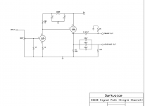
They actually look like cathode bypass caps. Im currently using 100uf/35V in Mu follower but in CF I guess we need 2.what is this Fitz mod?
https://www.head-fi.org/threads/dv-336se-hum-fitz-mod.353079/page-2
with DC im loosing all the bloom sounds kind of dry. Want to roll back to AC heaters but the hum is there.
Im attaching the schematic of the DarkVoice preamp
Please advice me where are these two 220uF caps are added.
Ill try them and update in here.
- Home
- Amplifiers
- Tubes / Valves
- 6SN7 Mu follower or cathode follower?