I can use the 6.3 tap on the 300BX to power the DC filament supplies (2). That tap has 6A and is just right. I won't use the two 1.2A 5V supplies. The second small transformer will be for the 4.2A of 6.3VDC I'll need. I'm thinking of going with my PreAmp power supply design (beefing up components to higher voltage values)l and adding a voltage doubler bias circuit. I'll probably configure the bias as jumper selectable for doubler or regular. I'll compliment that with two of my LV boards. You can see the boards I'm talking about if you look at HVFORLESS on Ebay.

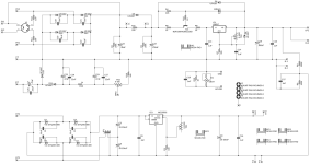
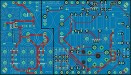
The power supply plan (and overall plan) is coming together. I realized I could take my PreAmp power supply PCB, add a bias circuit (with a doubler), and just beef up some of the front end HV components. I've attached the schematic and an Eagle screenshot of the board. I have a Poseidon MK3 setup that does a good job of sharing one adjustable bias between two power tubes. I'll incorporate that into the driver board shown on the screenshot from the Poseidon manual.
I think the easiest is a Hammond 300BX and a second small supply for the 300B filaments. I have some small regulated boards to hook up to those. If I was willing to go AC on those, I wouldn't need the extra power supply.
But, if anyone knows of a power supply that will do the trick please let me know. Also, please look at the attachments and let me know your thoughts.
Attachments
I would recommend Monolith Magnets for custom power transformers or alternatively Heyboer or Mercury Magnetics. All of these companies will build exactly what you needed.
I also recommended Rod Colemans DHT filament regulators. (I used to build my own, but his were better and cost is very reasonable.)
At 450V you may need somewhat more than -100V bias with current production 300B. My recommendations are EML 300B and JJ300B in that order. I have lots of experience with these and they are reliable and long lived. The later SV300B was a nice tube, early ones were highly prone to filament to grid shorts after a 100 or so hours of use. To their credit they replaced all of them (a dozen or so)
My advice would be to run with 400V, 3.5K primary and 70mA, that will give you about 8W. (The 17W in my view was highly optimistic and really runs the tube at the outer limits of its ratings.)
I currently run a pair of dual channel 300B / 6E6P amps with MM output transformers direct to my horns. (all active system) With 5K output transformers I get 6.5W at 2% thd, and way less at my typical <100mW power levels. (110dB horns)
Looking forward to pictures, etc as it comes together.
Edit: In looking at your filament regulator design I recommend you consider inrush current limiting during initial filament heating to maximize filament life, DHT filaments are not quite as well behaved in terms of inrush as most indirected heated tubes and this will impact service life. If you want to DIY I recomment looking at variants of the Ronan filament regulator, or going with the Coleman regs which take care of this problem. Mine are limited to rated operating current value (or as required to achieve 5V across the filament once fully heated) and I have achieved 10K hr operating times with JJ300B and now approaching that with EML tubes I currently use.
Last edited:
Great feedback. Thanks. Good news is I can play with B+ and bias with a twist of the screwdriver. And I'll get in touch with the sources you mentioned. If this is going to be expensive, it might as well be really expensive!
My LV regulated boards are basically the heater circuit on the attached file above. It makes use of the Micrel super low dropout LDO. It can get 5VDC out of 5VAC.
My LV regulated boards are basically the heater circuit on the attached file above. It makes use of the Micrel super low dropout LDO. It can get 5VDC out of 5VAC.
Why not 100V bias tap, and then you only need half wave rectification - simpler and more reliable.
Give yourself a little extra headroom on the DHT filament windings. 6 - 7 VAC even with the LDO protects against low line drop out, and improves regulator performance in most cases by provided more voltage headroom. Still use the lowest Vf diodes you can find. Drop out could result in audible buzz.
Same for driver stages if you plan to use DC to heat the filaments.
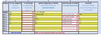
As an additional thought why not 117V and 125V taps or just 120V? Nominal mains in the U.S. is 120V and I only specify the 1 primary voltage. Consider dual 120V primaries if you think you might move in the future.
Mention that they were recommended by a couple of fan boys on diyAudio. 😀
Give yourself a little extra headroom on the DHT filament windings. 6 - 7 VAC even with the LDO protects against low line drop out, and improves regulator performance in most cases by provided more voltage headroom. Still use the lowest Vf diodes you can find. Drop out could result in audible buzz.
Same for driver stages if you plan to use DC to heat the filaments.
As an additional thought why not 117V and 125V taps or just 120V? Nominal mains in the U.S. is 120V and I only specify the 1 primary voltage. Consider dual 120V primaries if you think you might move in the future.
Mention that they were recommended by a couple of fan boys on diyAudio. 😀
Last edited:
The 800V secondary should say 0.2A, right? Right now it shows 200A.This is what I sent to Monolith.
Another thought, so what is your maximum intended plate current? If you are aiming at 70mA or more per tube 200mA (if AC rating) is marginal and I would recommend giving MM the maximum DC load current you envision and have them suggest a secondary rating for that. (Sorry I should have thought about this yesterday.)
There are certain specs in Electra Print iron to match them with their circuit designs. Iron from other manufacturers is not a perfect match to Jack Elliano's schematics. He has now authorised Kolarkar Audio Research to to build transformers of his design and I suggest that you contact them. They are very competent, have recently completed development of Z565 that matches the original on all parameters.Combed through the Electra-Print schematics and this caught my attention. I've been looking at it off and on for a few years and might move forward. I have a load of 6BL7 tubes so I don't care that they're obsolete. I have just as many 6BX7's that I could swap out. Power supply will need to be beefy. Other than that, it looks straight forward.
I love the simplicity and how hard it's being driven. Anyone ever heard of this being built?
Regards,
Similar but 6SN7 driven, stereo was too heavy so did dual monos:

Feedback welcome:
I worked up a schematic for the driver section in stereo. It's basically identical to the Electra-Print, but with some more detail to the bias. I'm also uploding my power supply schematic. I have that board fully laid out. I did have to tweak that board since I uploaded it earlier. I got rid of some options I didn't plan to use and resized the caps. I kept the doubler on the bias since I'll likely go with a stock power supply with a 50V tap. I'm not uploading the filament schematic right now. I plan to use some small regulated boards I already have for separate 5VDC to each 300B. I'll save that for a later discussion, but for now I want to focus on the PS and Driver.
I could use some eyes on the component values and rating on the driver circuit. I'd rather not go overboard on rating since I want to use metal film and stay as compact as possible. R4 was already called out at 5W (seems like a 2W would work). I called out R3 at 2W mainly to open up some higher voltage options (I believe I can drop in a 3/4W RN70 based on my math). For everything else I plan to use my stockpile of Dale RN60 (1/4 watt).
The big change is that I'm following much advice here and going with a B+ of 400V (70-80mA) instead of 450V (75mA). Are there any component values I should consider changing due to that shift?
Attachments
Sample:

ps. If the dissipation on resistor is 1W, use one at least four times bigger dissipation!
ps. If the dissipation on resistor is 1W, use one at least four times bigger dissipation!
@ero21, I really appreciate the simulation!!
I'm noting some differences in the circuit. Did you have this on hand from a previous design or did you tweak the Electra-Print schematic to assist with SPICE outputs.
I'm noting some differences in the circuit. Did you have this on hand from a previous design or did you tweak the Electra-Print schematic to assist with SPICE outputs.
Just put in my iron order to Monolith. 1590 Euro. Ouch! Customer power transformer, two output transformers, and one potted choke.
- Home
- Amplifiers
- Tubes / Valves
- 6SL7/6BL7 driven Electra-Print 300B