Power transformer info and order details are attached. If anyone wants to duplicate the order just see below.
I'll upload full circuit and PCB details soon for review. The plan is a separate PS board, two filament boards, and a driver board. They all fit together like a nice puzzle. Designs are 99% complete. I've already posted some drafts and things have changed very little since then.
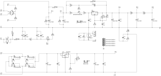
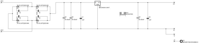
Power Supply details follow: The input tubes draw 1.8A total so that 6.3VAC circuit is sized to 3.6A. The two filament circuits draw 1.2A each so they are sized at 5VAC and 2.4A each. My low volt circuits use a super low dropout rectifier and schottky diodes. 5VAC ends up at 5VDC and 6.3AC ends up at 6.3VDC. No need to start higher. For the HV I went with 400-0-100-400 @ 250ma. I already designed a doubler for the bias circuit and may or may not keep it. It's easy to wire it up with the doubler disabled. My thought of keeping it are that I'll end up with some extra boards and someone may want the doubler if they're using a stock PS with a 50V tap. Anyway, more on the final circuits in a few days when I post them.
Also, I just received some Audio Note 0.47uF 630Vdc Copper Foil Series Mylar Oil Capacitors. I know everyone has favorite caps, but I'm locked into these at this point.
I'm looking hard at the Khozmo 51k Stepped Attenuator on the input instead of the recommended 40k resistors from the Electra-Print schematic. Room in the chassis could be a consideration. If someone sees logic for a value other than 51k please let me know your thoughts.
I'll upload full circuit and PCB details soon for review. The plan is a separate PS board, two filament boards, and a driver board. They all fit together like a nice puzzle. Designs are 99% complete. I've already posted some drafts and things have changed very little since then.
Power Supply details follow: The input tubes draw 1.8A total so that 6.3VAC circuit is sized to 3.6A. The two filament circuits draw 1.2A each so they are sized at 5VAC and 2.4A each. My low volt circuits use a super low dropout rectifier and schottky diodes. 5VAC ends up at 5VDC and 6.3AC ends up at 6.3VDC. No need to start higher. For the HV I went with 400-0-100-400 @ 250ma. I already designed a doubler for the bias circuit and may or may not keep it. It's easy to wire it up with the doubler disabled. My thought of keeping it are that I'll end up with some extra boards and someone may want the doubler if they're using a stock PS with a 50V tap. Anyway, more on the final circuits in a few days when I post them.
Also, I just received some Audio Note 0.47uF 630Vdc Copper Foil Series Mylar Oil Capacitors. I know everyone has favorite caps, but I'm locked into these at this point.
I'm looking hard at the Khozmo 51k Stepped Attenuator on the input instead of the recommended 40k resistors from the Electra-Print schematic. Room in the chassis could be a consideration. If someone sees logic for a value other than 51k please let me know your thoughts.
Attachments
Slightly unrelated but worth mentioning. The gods appear to be smiling down on me. I just scored a perfectly fuctioning Hickock 600A on Craigslist close to home for $200.

PLEASE TAKE A LOOK:
I'm very open to feedback. Ideally, I'm not being sent back to the drawing board with an idea from left field. So please frame things in a way that gets me to the finish line. I did receive some feedback early on about inrush from the filaments. I don't see the vast majority of designs trying to fix that. However, I am open to options that could fit on the filament board. That one isn't very densly populated. There's also some unused real estate on the driver board if needed.
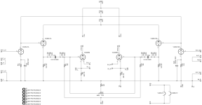
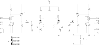
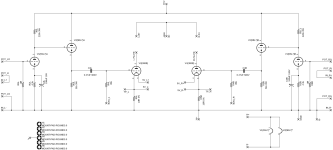
The driver board is 11"X3", power supply board is 7"X4", and the filament boards are 2"X4". Arranged, everything is 11"X7". All sockets are on the boards so this is a tidy setup and will it be a really clean build inside the chassis. Everything comes to the boards for wiring. I went with separate boards in case something needs to be tweaked. I'd rather not pull out the whole thing and start over. Also, I might do another version of the driver board to work with a traditional 6SN7 design and cathode bias. For now I'm going with something slightly unconventional, at least when it comes to the driver tubes (6SL7 & 6BL7), cathode follower, and fixed bias. There are no shortages of 6BL7 NOS tubes on Ebay for cheap so no worries there.
The board designs are pretty clean. No vias. Full ground plane for the filament board. There's a split ground plane for the power supply board. The driver board was harder than I thought it would be. If each channel took over a single 6SN7, then it would have been much easier. Using half of each driver tube for each channel made routing and layout a little bit of work even with all the unused space.
Please, someone look at my bias method. This is something you'd see on a push-pull. I'll have three test points and two pots that are all available from the top. Multimeter leads will go into the left and right positive to zero them out with the pot on the driver board. Then one of the leads will go into the ground to bring the average bias to the desired state with the pot on the power supply board. I have this on some KT88 monoblocks and it works nicely. I can bias them in about 60 seconds. I've never seen this for a SET stereo, but why not. Or maybe it's a horrible idea.
I'm very open to feedback. Ideally, I'm not being sent back to the drawing board with an idea from left field. So please frame things in a way that gets me to the finish line. I did receive some feedback early on about inrush from the filaments. I don't see the vast majority of designs trying to fix that. However, I am open to options that could fit on the filament board. That one isn't very densly populated. There's also some unused real estate on the driver board if needed.
The driver board is 11"X3", power supply board is 7"X4", and the filament boards are 2"X4". Arranged, everything is 11"X7". All sockets are on the boards so this is a tidy setup and will it be a really clean build inside the chassis. Everything comes to the boards for wiring. I went with separate boards in case something needs to be tweaked. I'd rather not pull out the whole thing and start over. Also, I might do another version of the driver board to work with a traditional 6SN7 design and cathode bias. For now I'm going with something slightly unconventional, at least when it comes to the driver tubes (6SL7 & 6BL7), cathode follower, and fixed bias. There are no shortages of 6BL7 NOS tubes on Ebay for cheap so no worries there.
The board designs are pretty clean. No vias. Full ground plane for the filament board. There's a split ground plane for the power supply board. The driver board was harder than I thought it would be. If each channel took over a single 6SN7, then it would have been much easier. Using half of each driver tube for each channel made routing and layout a little bit of work even with all the unused space.
Please, someone look at my bias method. This is something you'd see on a push-pull. I'll have three test points and two pots that are all available from the top. Multimeter leads will go into the left and right positive to zero them out with the pot on the driver board. Then one of the leads will go into the ground to bring the average bias to the desired state with the pot on the power supply board. I have this on some KT88 monoblocks and it works nicely. I can bias them in about 60 seconds. I've never seen this for a SET stereo, but why not. Or maybe it's a horrible idea.
Attachments
-
 300B Power Supply (Schematic).png217.1 KB · Views: 86
 -
 300B Filament Supply (Schematic).png89.4 KB · Views: 91
 -
 300B Driver (Schematic).png209.6 KB · Views: 90
 -
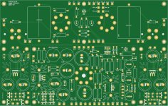 300B Gerber View (Merged).jpg420.4 KB · Views: 86
 -
 300B Power Supply Gerber View.jpg327.2 KB · Views: 56
 -
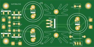 300B Filament Supply Gerber View.jpg122.4 KB · Views: 53
 -
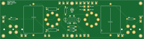 300B Driver Gerber View.jpg111.8 KB · Views: 72
Big mistake in first stage anode load!
220k is not the part of PSU, but 6SL7 anode load resistor, so if you use C19 capacitor, the anode AC shunted to gnd!
The anode load resistor must be close to the socket pin 2 to prevent oscillations.
BTW what's the role of TR1 and R6?
It generates crosstalk between channels, but does nothing with fixed bias DC voltages of channels.
p.s.
While not use individual bias for each channels?
Even "paired" new tubes requiring different fixed bias voltage, the used tube are mainly.
Thanks for the feedback. I made the 220k and C19 change after seeing the SPICE simulation. I'll undo those changes. Same thoughts with R11 and C15 that I added to the power supply?
TR1 and R6 is the bias approach I borrowed from the KT88 Poseidon I have. I'll upload the docs for your review. I thought it was a risky approach. I'll look at individual bias for each channel.
TR1 and R6 is the bias approach I borrowed from the KT88 Poseidon I have. I'll upload the docs for your review. I thought it was a risky approach. I'll look at individual bias for each channel.
Last edited:
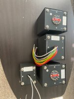
Over $2K worth of Monolith iron sitting in my office right now. I was lucky enough to help Make America Great Again by handing the UPS guy a tariff check for $200. Odd, but that didn't feel great for some reason.
I believe I have Euro21's feedback fully incorporated. Thank you!! Each channe is biased separately now. Plans are to jumper R18 and leave C19 and C20 unpopulated. I assume the issue remains with the C19 capacitor shunting the anode AC to ground if left in. I have the B+2 in there if I need to pivot to another design that needs a lower voltage for the driver tubes. I'm trying to keep this power supply as universal as possible for 300B designs.
All boards are designed so I can change my approach to this project with minimal impact if needed. If I need to switch to a 6SN7 or some other design, it should just be minimal part changes on the power supply board and then drop in a new driver board.
Feedback welcome before I pull the trigger on the PCBs and a large Mouser order.
One other unanwered question is regarding the attenuator I plan to order. I'd like to try this with and without a preamp. The original Electra-Print schematic has a 40K resistor at the input. I was planning on a 48 step Khozmo 51K attenuator. I see that 100K is the most popular choice with almost every 300B design I see. What are the pros/cons of going with 10K or 51K or 100K? The choices open up if I don't have to aim close to the 40K in the original design.
Chassis design to follow once this is proven out on the bench.
Attachments
-
 IMG_3001.jpg548.5 KB · Views: 52
 -
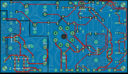 300B Power Supply.png1.5 MB · Views: 52
 -
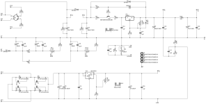 300B Power Supply Schematic.png242.6 KB · Views: 40
 -
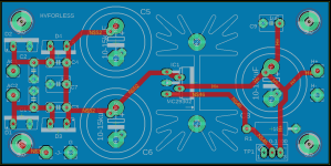 300B Filament Supply.png109.4 KB · Views: 40
 -
 300B Filament Supply Schematic.png89.4 KB · Views: 39
 -
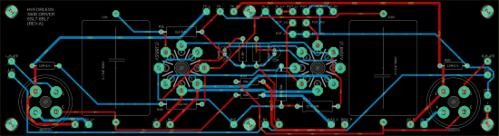 300B Driver.png483.6 KB · Views: 45
 -
 300B Driver Schematic.png190.3 KB · Views: 52
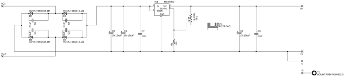
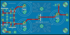
Small change to the filament supply to simplify things. I'm now using a MIC29150-5.0WT LDO. It's fixed at 5V and has overcurrent protection at 1.5A. This seems like an easy way to manage inrush at startup. I also moved a few pads around on the power supply and driver boards to allow for terminal blocks if desired.
Feedback I'm still hoping to get:
Feedback I'm still hoping to get:
- Any downside from the last RC filter in the power supply that feeds the driver tubes? Anode AC shunted to ground was a previous comment when I had separate RC filters before the 6BL7 and the 6SL7. It's easy enough to jumper R18 and leave C19 and C20 unpopulated and stay true to the original design. Seems like there could be an advantage with the RC to decouple from the B+ going to the 300Bs.
- Pros/cons of using different value attenuators (50k, 100k etc)? The original design has a 40k resistor on the input.
- Ground or float the filament power supply? I've read both being done as well as a small value resistor to ground.
Attachments
The Rod Coleman filament supplies are highly regarded and will some risk of your unproven design. Wouldn't it be easier to buy them instead?
Go with 100K, there is no reason to lower the first tube grid leak resistance that low. It just makes the amp harder to drive. If using an attenuator or a pot, I would add an additional 1 meg grid leak, in case the pot/attenuator wiper fails, there is still a grid to ground path.
The tariffs are great! I've paid over $1500 of them so far this year and love knowing I am doing my part to help reduce taxes for billionaires 🙂
The tariffs are great! I've paid over $1500 of them so far this year and love knowing I am doing my part to help reduce taxes for billionaires 🙂
Stephe, thanks!
Regarding filament supply, this is a proven design. Thousands of the adjustable version have sold on eBay over the last 10 years. Look up the seller hvforless (me).
Regarding filament supply, this is a proven design. Thousands of the adjustable version have sold on eBay over the last 10 years. Look up the seller hvforless (me).
I was talking about a 1 meg resistor from the grid of the first tube to ground.Stephe, thanks!
Regarding filament supply, this is a proven design. Thousands of the adjustable version have sold on eBay over the last 10 years. Look up the seller hvforless (me).
Stephe, already worked it in. Thanks again for the tip. See attached.
Still thinking about the attenuator. Choices, choices, choices. The most straightforward is a series type 100K. Ladder and shunt start to look more interesting though, because of only two resistors in the path. The downside is the variable input impedance to the signal source with a shunt. Ladder seems to be the best but options are limited. Not a lot of folks making ladder attenuators it seems. Khozmo in Poland is the only one I can find that I could kinda afford and they only offer a 10K version.
Still thinking about the attenuator. Choices, choices, choices. The most straightforward is a series type 100K. Ladder and shunt start to look more interesting though, because of only two resistors in the path. The downside is the variable input impedance to the signal source with a shunt. Ladder seems to be the best but options are limited. Not a lot of folks making ladder attenuators it seems. Khozmo in Poland is the only one I can find that I could kinda afford and they only offer a 10K version.
Attachments
I’ve bought one of these:
Taiwan made attenuator
And I’m really pleased with it, for my new project I ordered one with the blue dale resistors. It’s the L type so only two resistors in the signal path.
Taiwan made attenuator
And I’m really pleased with it, for my new project I ordered one with the blue dale resistors. It’s the L type so only two resistors in the signal path.
- Home
- Amplifiers
- Tubes / Valves
- 6SL7/6BL7 driven Electra-Print 300B