I need to design a 6SJ7 stage with about a gain of 50. -1v bias.
Here is what i came up with:
Supply voltage 60v
screen voltage 25v
Plate resistor 30K
Screen resistor 70K
Screen bypass resistor .22uf
cathode resistor about 500 ohms.
i don't care about distortion.... just looking for the gain and some pentode character.
Will be driving a 1M load.
Thoughts?
Thank you in advance!
Run a Google search for Norton equivalent circuits of pentodes.
Gain in a common cathode pentode amplification stage is approx. = (gm) (net AC load impedance). Per the 6SJ7 data sheet, the 6SJ7's gm is roughly 1.6 mA./V. Therefore, to get a gain of 50X, the net AC load impedance should be 31250 Ω.
BTW, I think the voltages you gave are too "short".
Gain in a common cathode pentode amplification stage is approx. = (gm) (net AC load impedance). Per the 6SJ7 data sheet, the 6SJ7's gm is roughly 1.6 mA./V. Therefore, to get a gain of 50X, the net AC load impedance should be 31250 Ω.
BTW, I think the voltages you gave are too "short".
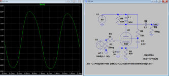
i am not going to use an inductor.
I also want to be able to push into the non-linear regions with a load of approx 30K. Thats why i had the screen voltage and plate voltage way down.
Also, i am looking to be right at the knee or even a bit lower.
Like i said i don't care about distortion... the more the merrier. Looking for grid bias of -1v . 30K load. gain about 50. right around the knee on the curves and a sort of symmetrical gain.
i am not going to use an inductor.
I also want to be able to push into the non-linear regions with a load of approx 30K. Thats why i had the screen voltage and plate voltage way down.
Also, i am looking to be right at the knee or even a bit lower.
Like i said i don't care about distortion... the more the merrier. Looking for grid bias of -1v . 30K load. gain about 50. right around the knee on the curves and a sort of symmetrical gain.
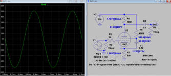
Top gain cannot be more than 25!, below 0.3V can get gain of 50 though, symmetrical gain, distortion < 7%
Attachments
Last edited:
You will probably need a screen voltage closer to 60V to get a gain of x50 with a 30k anode resistor. At 25V you will probably need a 100k anode resistor, or even more. If the screen is fed from a large resistor (as you're planning to do) then there will be no harm in using a higher screen voltage, even if you overdrive the tube.
Thanks merlin!
I have your book and I am trying to wrap my head around it. So I am trying to get good screen compression, low gain around 50 and good pentode sound. It's for first stage in a guitar amp.
Isn't 100k a higher gain than 50?
Thanks!
I have your book and I am trying to wrap my head around it. So I am trying to get good screen compression, low gain around 50 and good pentode sound. It's for first stage in a guitar amp.
Isn't 100k a higher gain than 50?
Thanks!
The gain is equal to gm * Ra. The gm depends on screen voltage and bias voltage. On page 4 you can see a graph showing transconductance against bas voltage, for various screen voltages:Isn't 100k a higher gain than 50?
http://www.soemtron.org/downloads/disposals/6sj7.pdf
There isn't a 25V curve but you can eyeball it, and I reckon it wouldn't climb much higher than 1000 micromoh (1mA/V). At a typical 'middling bias' you would be operating would be further down the slope of the curve, at perhaps 0.5mA/V, which when multiplied by 100k gives you a gain of 50.
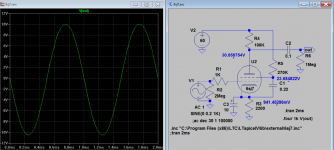
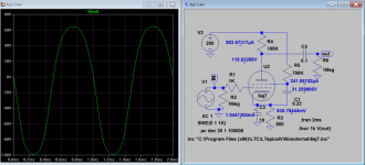
so how about:
200v supply
-1v grid bias
25v screen
plate current about 1mA
screen current about .25mA
100K plate resistor
700K screen approx.
800 ohm cathode resistor
this is as a starting point.
200v supply
-1v grid bias
25v screen
plate current about 1mA
screen current about .25mA
100K plate resistor
700K screen approx.
800 ohm cathode resistor
this is as a starting point.
so how about:
200v supply
-1v grid bias
25v screen
plate current about 1mA
screen current about .25mA
100K plate resistor
700K screen approx.
800 ohm cathode resistor
this is as a starting point.
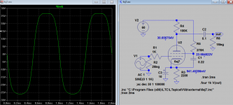
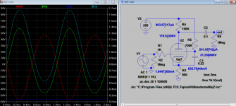
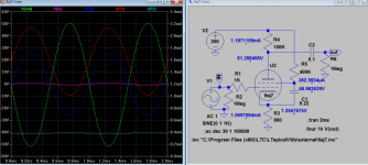
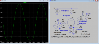
My sim match your data very closely, have nearly uniform gain 50 up to 1V pk input, distortion < 5%, good to go?
Attachments
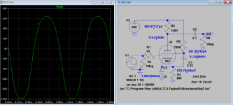
I don't see a cathode bypass cap on those sims.
I omit it as it gives more linear gain of 50 which you requested. If it's in, it is non linear gain from 100 at 0.1V to 60 at 1V and noted that min cap is 10uF, if change to 100uf out is still same gain pattern 100 to 60.
Attachments
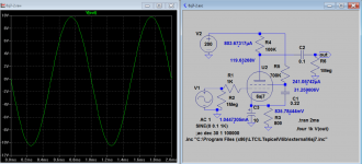
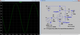
I do want the non linear gain.
Yes, just omit the bypass capacitor will give more linear gain. Raise the screen to 47V give more symmetry and linear gain 50 at 1V and 47 at 1.5V which exceeded your requirement. If you put 10uF bypass cap the gain shoot up to 100 at 0.1V and 80 at 1V which is quite non linear? If you keep HT at 200V and lower screen voltage with 10uf bypass cap give you even more non linear gain 100 @0.1V and 60 @1V. But it is not very symmetric at lower screen voltage.
Attachments
Last edited:
- Status
- Not open for further replies.
- Home
- Amplifiers
- Tubes / Valves
- 6SJ7 gain setup