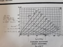
Triode strapped SET output stage: 6P6S and 6P1P-EV
Today I got some time to try an output stage based on some Reflektor 6P6S I bought a few weeks back (before the world stopped turning).
I built a test board, some weeks ago with sockets for each valve model, so it should allow easy comparison between the two valves.
Initial results with the 6P6S are quite encouraging. I have yet to try the 6P1P.
Setting up a self biased stage, fully bypassed cathode resistor, using a Jan Western 4k/5k OPT.
B+ used was 250V and 300V. Anode to G2 connection via 220R resistor.
Rk of 820R, bypassed by 470uF gives Vg of approx -22V, and about 25mA anode current, in quiescent condition.
Using this setup, the output stage gain is in the region of 5.5 V/V. (Open loop)
Working backwards, for 1W into 8R on the secondary (3V RMS) requires about 99V swing on the primary - probably about the maximum clean voltage swing, using a triode on 300V HT. (5k primary wdg)
Using a small transformer to step up voltage into the output stage, since the signal generator is limited to 7V RMS, and observing the input voltage with an oscilloscope, and I require about 16V RMS drive to reach just over 1W output.
Next ideas to try:
0, try an equivalent circuit with 6P1P.
Or...
1, LED cathode bias at 22V, or more perhaps, in order to accommodate a larger input signal.
2, connect G2 to the unused 4k OPT tap, for about 10% distributed loading - expecting more gain and output, how much? Who knows?
3, cathode CCS (more work)
Any ideas other than these?
Which one should I try first?
Any and all input welcome.
Stay safe folks
Last edited:
One way or another, I need a preceding gain stage.
I have some used ECC88, I need to test, which could provide some of that gain. If they work.
I have plenty of subminiature 6N16B, 6S6B - in keeping with the Soviet theme.
Maybe 😱
Some silicon gain stage a the input.
Maybe 😱
Some global feedback used in the silicon input stage?

Is that heresy?
I have some used ECC88, I need to test, which could provide some of that gain. If they work.
I have plenty of subminiature 6N16B, 6S6B - in keeping with the Soviet theme.
Maybe 😱
Some silicon gain stage a the input.
Maybe 😱
Some global feedback used in the silicon input stage?
Is that heresy?
I bought a few dozen years ago for $2 each.
I used them in Magnavox push pull and se amps, dared push pull amps and several custom amps. They worked fine in all of the amps.
I torcher tested them in an SE test rig with Schade style feedback and 350volt HT. I got just under 5 watts at clipping and no red plating.
I used them in a bi-amp system in SE driving an ESS AMT. I was very satisfied with this arrangement and used it for many years.
I got a good buy on a 300B SE amp. I connected it to the AMTs to test it and it immediately became permanent.
If I didn't have the 300B amp I would still be using the 6P6S' in SE to drive the AMT.
Steve
I tried them triode strapped and got 1+ watts. They sounded very good.
I couldn't hear a difference between triode strapped and Pentode with Schade Feedback. So, I stuck with the Schade feedback version because of the greater power output.
The SE Amp setup was down 3db at 45khz.
FYI: I had my hearing tested. One ear is good to 10khz and the other to 14khz. So your experience could easily be different than mine.
Member
Joined 2009
Paid Member
Thanks for the replies
Hi,
Thanks for the replies and experience shared!
At the moment I am running the load line for triode wired based in the datasheet Pd max values, Pa of 13, Pg2 of 2W, for Pd of 15W MAX.
My loadline is for a Pa of around 12W, about 80% maximum dissipation.
A little update:
1, I tried LED bias at up to Vg 24V, with no local FB, triode wired - I like the gain and the basic circuit works well enough for a Watt or two - depending where I decide THD is excessive! Almost all 2nd harmonic.
Adding local plate to grid FB and THD is a little better, albeit with the cost of increasing drive requirements.
I have a habit of using plate to grid FB absolutely everywhere, probably as I've never got global feedback working in one of my own home brew circuits.
But I got to those conclusions, in this case, by trying:
2, Using unused OPT tap as screen tap.
This didnt go so well. More gain as expected since I am no longer triode wiring the 6P6S, but marked increase in THD, in fact a heavily asymmetric output, still mostly 2nd harmonic.
Adding plate to grid FB here cleaned up the output asymmetry quite well, but open loop performance in triode was comparable.
I still havent tried a CCS 😀
Square wave response is a bit squirrely, 4 or 5 cycles of ringing to the edges !
I havent used a capacitor bypassing the grid to ground at RF, or capacitor in the LNFB loop to limit the gain with respect to RF, and my OPT shows some resonance in the 40-70kHz range.
Hopefully this edginess is due to me omitting those components, so I will have to add them and see what I can do about the ringing.
Last edited:
6P6S/6V6 family isn't suited well to this topology due to low transconductance. Indeed you'll get results comparable to the triode mode, but harder to drive.Adding local plate to grid FB and THD is a little better, albeit with the cost of increasing drive requirements.
I have a habit of using plate to grid FB absolutely everywhere, probably as I've never got global feedback working in one of my own home brew circuits.
Try adding 5W zener (I would say, 51V one, but feel free to experiment) in the screen grid circuit to drop screen voltage relative to the plate.Using unused OPT tap as screen tap.
This didnt go so well. More gain as expected since I am no longer triode wiring the 6P6S, but marked increase in THD, in fact a heavily asymmetric output, still mostly 2nd harmonic.
I havent tried a zener to drop x Volts from the anode supply, though I used a full zener divider to good effect before, with respect to regulating g2 in pentode/tetrode mode...
I have a feeling that either will work better than the crude UL implementation I tried briefly.
If I had the right OPT I'd likely move on to trying push pull, since what I seeing is a lot of mainly 2nd harmonic, which would be partially cancelled in push pull.
But regulation g2 may be the way to go for 2-3W at reasonable THD.
Sunday update
I tried zener regulating the screen grid, as suggested - using 1N53(38?) Two series 24V 5W zeners in series.
I didnt spend much time fiddling with values, but well, the output was better, but THD not.
So going back to Triode wiring the 6P6S, LED cathode bias at -22V give or take, and played with OPT tappings to optimise the output. B+ 340V, Ik of about 30mA.
5k:8R tap 8R load gave the highest output, but 2nd harmonic is only -18dB at 3.2V across the load.
So I switched to using one 4R tap and the other end of the load on the 8R tap - a nice median result, less output, 3.1V, better THD with F2 at -22dB
I'd guess this corresponds to a reflected load of about 7k, which is close to optimum for minimum THD for the 6P6S (according to datasheet)
Both cases I have u47 plate cap, and local NFB via 220k resistor (Ri of 22k)
Attachments
A quick experiment with 6P1P-EV and results are similar to 6P6S (perhaps I shouldn't be too surprised?)
Albeit the datasheet info indicates a lower tolerance for both anode and g2 volts, 250V.
Ignoring that and running at 340V and Vg of about -20V and I get very similar results to 6P6S..
I dont think it would do anything for their longevity however.
Now to think about input stage...
I was looking at 6N1P, 6N2P, 6N6P...
Well the datasheet curves for 6N1P and 6N2P dont look all that linear to me....what am I missing?
6N2P looks frankly pretty awful, though the scaling looks like this EV version is for impulse duty...
I guess I'd want something near to a 12AY7 or AT7... I dont want a phone stage....
6N3P and 6N5P look better, but hard to find...
Any suggestions?
Last edited:
6P6S/6V6 family isn't suited well to this topology due to low transconductance. Indeed you'll get results comparable to the triode mode, but harder to drive.
Yes I agree, I dont have enough experience to know why, but it is true enough.
Out putting roughly 5% THD at 1W output, mostly 2nd harmonic, isnt particularly good.
Can I ask, what approach is effective in applying feedback to a low transconductance device?
Feedback to the cathode of the driving stage from the secondary winding?
Or does this type of valve, suit open loop operation better?
Last edited:
I ended up using 6P6S in triode mode. That's good enough feedback type for me, clean 2 watts are easy to get.
And unlike many 6V6s, those are rugged bastards, rated 10% higher in terms of plate dissipation and happily living with 350-370V on plates (and second grids), so you can have even more watts, though you'll need some kind of even harmonics compensation (by deliberately unbalancing the driver stage, for example) to get decent total THD numbers.
And unlike many 6V6s, those are rugged bastards, rated 10% higher in terms of plate dissipation and happily living with 350-370V on plates (and second grids), so you can have even more watts, though you'll need some kind of even harmonics compensation (by deliberately unbalancing the driver stage, for example) to get decent total THD numbers.
I ended with 340V on the plate, and g2, 30 to 35mA quiescent current.
And that is in triode mode
I didn't get anywhere near 2 Watts...
Maybe I'm being too conservative with idle dissipation?
And that is in triode mode
I didn't get anywhere near 2 Watts...
Maybe I'm being too conservative with idle dissipation?
I suppose that my use of a input step up transformer could be contributing a large amount to the total THD, which I hadnt considered.
I should clarify that ideally I am only really interested in triode mode with the 6P6S, I have just been a little surprised and disappointed so far, given that I used a smaller output device (6P30BR) in pentode mode, and had an output approaching 1W, with much lower THD ( and the Pd max of the 6P30BR is roughly half the 6P6S)
I should clarify that ideally I am only really interested in triode mode with the 6P6S, I have just been a little surprised and disappointed so far, given that I used a smaller output device (6P30BR) in pentode mode, and had an output approaching 1W, with much lower THD ( and the Pd max of the 6P30BR is roughly half the 6P6S)
Last edited:
340V/42mA with fixed bias (-24..25V) should give about 2.4W (minus losses in OPT) to 4k load
With self-bias (510R or something about that) it should be around 1.9W at full drive
With self-bias (510R or something about that) it should be around 1.9W at full drive
Thanks for you help again TG. 🙂
I will have to try and achieve some more Volts then.
Currently my supply is limited to about 345V depending on current, using a variac (0-270V) to drive 230:230 isolation transformer, bridge rectified, then CRC (220u, 100R, 220u)
Also I am using LED cathode bias at about -24V, easy enough to change to self bias and 510R, however.
Fixed bias, isnt really an option, without adding another transfomer to generate the -ve rail - something i may need to look at!
I really need to get some CT OPT and try my first push pull valve stage - it's what I wanted the 6P6S for...but well...I have a fairly suitable SE OPT already - so that has governed the direction I went in
Thanks again, you've been helpful, and got me thinking....and these tubes are NOS, and maybe a little low on emission, I have another 3 to compare it with. At first glance though, they seem to be pretty close to expected, from the datasheet, regarding quiescent current, plate Volts and Vg1 etc.
Last edited:
You're welcome 🙂Thanks for you help again TG. 🙂
Not an issue really:Fixed bias, isnt really an option, without adding another transfomer to generate the -ve rail - something i may need to look at!

Ahh yes from the Valve Wizard site. 🙂
Surprisingly, I havent opened a book over the last few weeks, and havent bothered looking in either of the MJ or MB books I have.
Self bias has always just seemed "safe", which of course it is - the price paid being some loss HT.
Surprisingly, I havent opened a book over the last few weeks, and havent bothered looking in either of the MJ or MB books I have.
Self bias has always just seemed "safe", which of course it is - the price paid being some loss HT.
The input transformer
Well this input transformer was always a botch, to give me some voltage gain to drive the 6P6S from a function generator, without having to use an input gain stage - short term solution.
Running a FFT on the 6P6S grid input, while the heater, but not HT is on, was enlightening. At least 2% THD spread across the board F2 to F7.
Ok. So I pull out the 1st stage of my first valve amp build, a triode gain stage using 6S6B, which I've read is half a 6N16B (not sure how much truth is in that being as I read in on the www)
I removed all FB from that stage, running open loop, 2 series LED for cathode bias.
Then rewired the isolation transformer for 440V, and carefully wound up the variac to 360V or so.
Check voltages quickly and bunged the signal on.
0.8V RMS input now gives me 3.6V across the 8R load, before clipping.
Take an FFT....
Not bad!!!
A shade over 1% THD. (And this is still while using ineffective plate to grid LNFB on the output stage)
Sweeet
- Home
- Amplifiers
- Tubes / Valves
- 6P6S triode strapped output stage: first pass experiments.