A few calcs later and some adjustments and I can achieve about 1.7W at the secondary, by using 340V on the plate and -24V on g1.
I have experimented with local cathode degeneration, and found that performance was similar running the first gain stage open loop, without cathode bypass capacitor.
I also found what I thought was some significant improvement in THD.
Alas, I ran the numbers and it isnt so good.
With second harmonic at about -35dB and 3rd harmonic slightly below that, I reach 1.7W at a shade under 2% THD. (Rather than 1% as stated earlier)
The two gain stages, when set to what I believe to be optimal, constitute a very good THD measurement, definitely at 1% or lower, and I have loads of gain in hand.
To be honest, I am slightly disappointed in the result.
Perhaps it's now time for me to attempt something more than a 'stab in the dark' taking feedback from the Output stage above, back to the input stage grid.
Perhaps, using 6P6S/6V6/6P1P, a push pull triode stage will give far better THD at a similar power output.
Shame...now I need to consider that my OPT are cr@p, or buy some PP OPTs instead.
Last edited:
1.7W at less than 2% distortion for a triode strapped 6V6 is a good result.
Can you show a schematic of the output stage wherein you are using local feedback?
Steve
Can you show a schematic of the output stage wherein you are using local feedback?
Steve
It is?
I guess I expect too much?
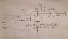
I'll see what I can rustle up regarding the schematic.
EDIT: just drawn a schematic, excuse my lack of drawing prowess!
I have to admit that I need to check dissipation again,
since changing the circuit a bit, but it should be less than 100%!
I guess I expect too much?
I'll see what I can rustle up regarding the schematic.
EDIT: just drawn a schematic, excuse my lack of drawing prowess!
I have to admit that I need to check dissipation again,
since changing the circuit a bit, but it should be less than 100%!
Attachments
It's been a while since I had time to play with this circuit.
Today I made some progress.
I had been soap boxing about trying some form of global feedback, but my half assed attempts in the past have been pretty useless.
Initially I tried feedback to the driver stage from output stage plate, but it needs more work; either it is less effective than I hoped, or there was just too much feedback, and I need to do some more maths/fiddle with feedback resistance.
Well today I tried global feedback from the OPT secondary to the input stage cathode (I reversed secondary connections so that there was another phase inversion) and a smallish amount of feedback cleaned the output up quite well.
In two iterations I tried removing the plate to grid local FB in the output stage, then put it back again - LNFB alone had worked OK, perhaps not as well as for higher gm devices (which I didnt know before this thread) but it got me perhaps another 4dB improvement.
I wonder...
What about combining plate to cathode FB between the output and driver stages, and then adding global feedback from inverted secondary to input stage cathode?
Would that work?
Would that work well?
I might find out soon!
Last edited:
Well it certainly works
If there any interest I will go ahead and post a schematic of the finished design, perhaps tonight, if I have the time to draw it!
Adding some feedback from the inverted secondary winding, to the input stage cathode, has worked some magic.
I took a FFT at max output, 4V across 8R (2W), and THD is in the region of less than 1%.
Distribution of harmonics is predominantly 2nd and 3rd only, and the levels stay pretty static until I get into the higher output power range, above 1.25W, where 3rd begins to climb with increasing output, where the 2nd stays pinned at -30dB.
It would seem a fortuitous level of harmonics cancelling between stages!
It was almost painful to perform the sine wave tests again, to confirm the THD level; since adding the global loop I have been caught up in just listening to this amplifier and enjoying the music.
The speakers I have used arent the last word in high fidelity, and there is little bass below 100Hz, so next I will be setting up some larger, harder to drive speakers, to judge the damping factor and audible effects it may have.
First I need to test again, to find the output impedance!
Sure. I have it partly drawn up and should finish it tonight/tomorrow.
Its LED or diode cathode bias throughout, which isnt something I'm sure I particularly like, or dislike - I'm very much still learning.
Also the design will probably change again, since I have some 6N2P, and 6N5P (6N3P shipping) and I thought possibly using 6N2P input stage, 6N5P driver stage may work out well.
But I just love the 6S6B, such a fantastic medium mu triode.
Hi Steve and anyone else reading
I have started a thread, now that this amp is almost finished, and open for constructive critique from the forum gurus
Schematic etc can be found here:
https://www.diyaudio.com/forums/tub...oking-constructive-criticism.html#post6239359
I have started a thread, now that this amp is almost finished, and open for constructive critique from the forum gurus
Schematic etc can be found here:
https://www.diyaudio.com/forums/tub...oking-constructive-criticism.html#post6239359
- Home
- Amplifiers
- Tubes / Valves
- 6P6S triode strapped output stage: first pass experiments.