Like others before me, I'm looking for an inexpensive and convenient sub for the 7868. Use case is a Bogen CBH35A.
6P41S has the right pinout, and close enough basing to work without having to change the sockets. Just needs a bias tweak to keep idle current manageable. But ... max voltage spec is 400V plate and 350V screen, while this amp runs 440V plate and 420 screen. Getting the screen in spec isn't hard - easiest option is to feed it from the 1/2 B+ node of the power supply (it's a doubler), and there are others. More concerned with the plate.
Has anybody run these higher than spec? +10% should be alright if I keep the screens reasonable, right?
The tube depot.com seems to stock equivalents to the 7868 but it wants me to enable javascript and it goes through Cloudfront so unless I disable stuff and let it identify and track me I will let you look instead of me .
How about the 6GM5 ?-
6GM5 9 Pin Beam Power Amplifier Tube
I can see why you don't want to pay for an original 7868------dear !
How about the 6GM5 ?-
6GM5 9 Pin Beam Power Amplifier Tube
I can see why you don't want to pay for an original 7868------dear !
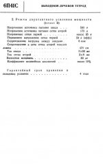
Experience from practice shows that the 6P41s tube withstands a voltage of 500V and even more at the plate, if the voltage G2 is fair low and the current is controlled by a negative bias voltage G1.
Attached is a page of the original Russian manual for the 6P41S tube and information on the push-pull output stage (unfortunately, it is in Cyrillic!).
Attached is a page of the original Russian manual for the 6P41S tube and information on the push-pull output stage (unfortunately, it is in Cyrillic!).
Attachments
How about the 6GM5 ?
Interesting! Unfortunately, they're $25 apiece, and I'd need to change the sockets. That gets me a quad of 6P41S ... just have to wait for shipping from Ukraine or Russia.
Experience from practice shows that the 6P41s tube withstands a voltage of 500V and even more at the plate, if the voltage G2 is fair low and the current is controlled by a negative bias voltage G1.
Attached is a page of the original Russian manual for the 6P41S tube and information on the push-pull output stage (unfortunately, it is in Cyrillic!).
That's great to know. So you've built (or used) an amp that abuses the specs like that?
Tubes do not blow-up right away at a mere 10% over voltage.
And these are 4 bucks each! Buy a pair and a spare.
And these are 4 bucks each! Buy a pair and a spare.
Tubes do not blow-up right away at a mere 10% over voltage.
And these are 4 bucks each! Buy a pair and a spare.
True, but I also know that some tubes are more ... delicate? ... than others, so it can't hurt to ask. Then again, I've yet to hear of a Russian tube that can't handle being abused.
I'ma buy a quad!

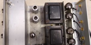
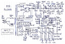
I replaced the 7591 tubes (very similar to the 7868 tubes) with 6P41S at the service of 2 amplifiers: "Scott LK72" and "Fisher X202C" where they work very well, maybe even better than the original 7591. Of course the voltage on G2 is stabilized at 150V and the negative voltage voltage G1 adjusted according to the criterion of the smallest distortions.

Attachments
-
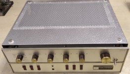 2022-06-21-sa poklopcem_1024x586.jpg160.2 KB · Views: 239
 -
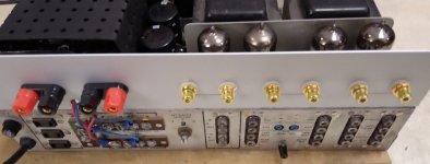 20220618_124218_1024x460.jpg62.8 KB · Views: 184
 -
 20220618_124145_1024x460.jpg68.9 KB · Views: 211
 -
 Scott-LK72-PS-new.jpg467.3 KB · Views: 285
 -
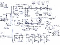 Fisher X202c-ps-a_1024_768.jpg196.4 KB · Views: 321
 -
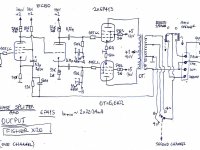 Fisher X202c-output-a_1024_768.jpg152.2 KB · Views: 349
This project got put on the back burner. Counting my current project, it's now third in line. I should get to it in November at my current pace.Hey Deafen,
If you can hear me, could you report back what you found.
6GT5 has the same pinout; even lower screen limit though. Best part is that it won't stretch out the socket pins like the 6P41S (or EH 7868).
I was thinking about the “screen grid sensitivity” of the 6P41S (and even worse 6GT5 - thanks Tom) compared to the 7591/7868 family, and I am trying to understand the tube anatomy that is at play here. Why is the 6P41S not able to take the screen grid voltage a good 7591 (NOS or recent) can?

Is it purely the proximity of the screen grid to the control grid? Does that also determine the transconductance? And gain?
My question is: Since the 7591 and 6P41S have similar transconductance (IIRC) why can the 7591 live happily with 400+ volts on the screen, while the 6P41S is limited to ~170 V? I must be missing something.
Also don't get it. Think of 6L6GC and 807 screen voltage ratings: 450 V vs. 300 V with almost the same internal structures.
Best regards!
Best regards!
A clarification: In my post #14 I used an illustration of a pentode. I should have used a tetrode, since the 6P41S is a tetrode, but couldn’t find one in my haste. The point/question is still valid, though.
After a bit of further digging I found a thread on 6P41S vs. 7868, and specifically a post by member #The Gimp that translates the original 6P41S data sheet into English. They are attached in post#50
https://www.diyaudio.com/community/threads/6p41s-vs-7868.318550/post-5424804
After a bit of further digging I found a thread on 6P41S vs. 7868, and specifically a post by member #The Gimp that translates the original 6P41S data sheet into English. They are attached in post#50
https://www.diyaudio.com/community/threads/6p41s-vs-7868.318550/post-5424804
The screen can be operated well above 170V. Max listed in the data sheet is 350.
Forget the 14W plate dissipation, the tubes don't red plate until way higher than that. Looking at my notes, I hit 30W plate dissipation when they started to red plate (125mA at 240V).
I dont think that the internal construction has anything to do with it.My question is: Since the 7591 and 6P41S have similar transconductance (IIRC) why can the 7591 live happily with 400+ volts on the screen, while the 6P41S is limited to ~170 V? I must be missing something.
There won' t be any flash over in a vacuum just because of voltage as such, no gas assumed.
The limit in the ds is 350v anyway, and I just happen right now to listen to an amp with 6p41s triode connected 400v on both plate and screen, 20W total.
I believe the numbers shown on p.3 of the ds are just picked such that they go together well:
for the listed power out into 8k load p-p you need 500v on the plate and 24v rns signal on g1, which is 34v peak; so -35v g1 bias is a good choice; but now you cannot have 400v on g2, but 170v is what is required to stay within dissipation limits;
and that is what the single example in the ds shows, it just fits the bill ...
on the other hand, 500v plate and 400v g2 would force you to bias g1 at what ? -70v or even more negative, plus -34v signal and you end up at -105v on signal peaks and at the same time "waste" 35v at the other end ...
if you can only have one example shown in your ds you have to make a choice ...
I think it has to do with the pitch of the screen grid - a more tightly wound grid will attract more electrons and dissipate more power. A looser screen grid winding can operate at a higher voltage and has to to get the same peak cathode current. Triode connection is easy on the scree, as the plate never drops below the screen voltage as it does in pentode mode - the highest dissipation condition for the screen.
Hi Tom,
regarding my 6L6GC vs. 807 example, I don't think so. Both these power tubes basically share the same sets of plate curves, so we have to assume that the screen pitch also is the same for both.
Best regards!
regarding my 6L6GC vs. 807 example, I don't think so. Both these power tubes basically share the same sets of plate curves, so we have to assume that the screen pitch also is the same for both.
Best regards!
- Home
- Amplifiers
- Tubes / Valves
- 6P41S / 6∏41C at high voltage?