That splitter with the common mode feedback is curious. But does it really equalize the phases?
Seems to me that it would just change the overall gain since it acts the same for either phase. It does the same thing for either phase up until one side exceeds the peak reached by the other side, so the signals must have the same gain up till then.
Seems to me that it would just change the overall gain since it acts the same for either phase. It does the same thing for either phase up until one side exceeds the peak reached by the other side, so the signals must have the same gain up till then.
Hello fellow diyer from North Carolina (home of Nascar BTWThat splitter with the common mode feedback is curious. But does it really equalize the phases?
Seems to me that it would just change the overall gain since it acts the same for either phase. It does the same thing for either phase up until one side exceeds the peak reached by the other side, so the signals must have the same gain up till then.
") )!
)!There is a good explanation on this topi over at Kaizer Power electronics website.
100W 6P45S monoblock tube amplifier | Kaizer Power Electronics << this one.
A fellow forum member - Kruesi - proposed this idea a while ago, and what I did was to replicate it, and implement it myself, with good results.
I've run countless hours of simulations over the topic, and it seems to be the right choice. You simply do not need "hand picked" (read that, overpriced) tubes for the phase splitter. At least if the tube is inside a decent level of (dis)similarity between the two triodes. A couple of percents of tolerance can be easily overcome by this design. At least this is what I've experienced so far with some really worn 6N1P. When I was still having passive cathode current source (resistor), I had difference of even 10% or so between the two sides. With this approach, this became irrelevant, and the discrepancies in the measurements were sub 1%. I've tried a couple of more tubes, and it was always balanced within a reasonable margin.
Last edited:
The linked explanation is interesting. But still puzzling.
I think if the two triode Mu's are not matched, the cathode voltage will automatically swing around to equalize the outputs, even without the common mode feedback link to the constant current source in the tail.
With a CCS in the cathode tail, any current drop on one side must be met with an equal current rise on the other side. (the cathode tail voltage will vary to insure that if the Mu's or gm's are different) With equal AC currents and equal load resistors, the output levels have to match (but inverted). I'm still trying to figure out what the common mode feedback is doing that isn't already solved. I think it may just act as an auto bias scheme to set the average plate voltages.
Last edited:
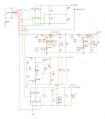
I had made some developments on the G2 power supplies. On the original design, the regulation was not so great, I had variations of around 4-5V with temperature. Those high voltage zeners are very sensitive to temperature.
Then I came up with this contraption:

This way I get a pretty tight regualtion, it's around 10ths of volts. If using around 220-270V at the input, the output will be adjustable between 110 ans 230 V. This at a load at around 40-50mA, which is well for the purposes of this amp (supply for G2s).
Then I came up with this contraption:
This way I get a pretty tight regualtion, it's around 10ths of volts. If using around 220-270V at the input, the output will be adjustable between 110 ans 230 V. This at a load at around 40-50mA, which is well for the purposes of this amp (supply for G2s).
So, as Mads made some updates about his 6P45S amp, here is it's little brother based on the glorious 6P36S (at least by my standards).
I got a couple of new stuff since the last update.
Most important, a rebuild of the amp, and then a pretty fine Creative XFi soundcard, 24bit/96kHz, which I'm using to measure things using the ARTA suite.
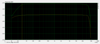
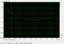
So, what we've got here are some graphs taken at 8V and 24V output over a 8ohm dummy load. Frequency response and THD measurements (by Steps from ARTA). It's obvious that the OPT, TGL40, is hurting below 30Hz - which is actually not a problem for me, as I wanted this amp for music.
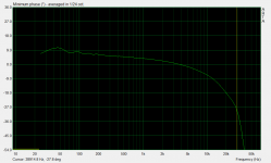
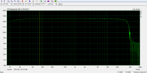
Then a phase graph, and a white noise FR measurement.
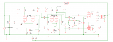
I've uploaded the current amp configuration for reference. What I found was that running the input section at ~200V gives better THD at high frequencies (above 10kHz).
The power supply is a toroidal PT, bridge rectifier, G2 supply from center tap of the PT. Adjustable regulators for G2, driver and input stage voltages are available, so there is some level of freedom to do some tweaking.
Idle current was 25mA while taking the measurements. I realized that it's still ok (I was using 30mA ~15W Pda), the amp runs cooler, and there are no noticeable side effects.
I got a couple of new stuff since the last update.
Most important, a rebuild of the amp, and then a pretty fine Creative XFi soundcard, 24bit/96kHz, which I'm using to measure things using the ARTA suite.
So, what we've got here are some graphs taken at 8V and 24V output over a 8ohm dummy load. Frequency response and THD measurements (by Steps from ARTA). It's obvious that the OPT, TGL40, is hurting below 30Hz - which is actually not a problem for me, as I wanted this amp for music.
Then a phase graph, and a white noise FR measurement.
I've uploaded the current amp configuration for reference. What I found was that running the input section at ~200V gives better THD at high frequencies (above 10kHz).
The power supply is a toroidal PT, bridge rectifier, G2 supply from center tap of the PT. Adjustable regulators for G2, driver and input stage voltages are available, so there is some level of freedom to do some tweaking.
Idle current was 25mA while taking the measurements. I realized that it's still ok (I was using 30mA ~15W Pda), the amp runs cooler, and there are no noticeable side effects.
Attachments
Hey mcl2k6
My measurements turned out to be invalid, dummy load was not connected so the amplifier was driving into 100K of the analyzer :/
Is your new power supplies regulated or do you have to adjust them yourself? I got completely rid of the screen MOSFET linear manual regulation as if kept getting destroyed at power on, its now all replaced by a 220K resistor that do the job just as fine
Hey mcl2k6
My measurements turned out to be invalid, dummy load was not connected so the amplifier was driving into 100K of the analyzer :/
Is your new power supplies regulated or do you have to adjust them yourself? I got completely rid of the screen MOSFET linear manual regulation as if kept getting destroyed at power on, its now all replaced by a 220K resistor that do the job just as fine
Yeah, I happened to have a similar measurement brain fart when measuring my chipamp. I was getting strange results, until I realized that there was no load connected.
As you can see from the schematic above, G2 is regulated, but I opted to have a trimpot, to be able to adjust the output. It's possible to do 130-240V.
Also, the phase splitter and the driver do not derive their voltages by a resistor dropper, but they received two small regulators, also adjustable. These are practically in series, the first one for the driver drops the B+ to some 425V or so, then the second one, for the LTP, brings this voltage further down to 200V now.
I never had any issues with Mosfets blowing up, however I use 2SK2645, which are rated at 600V, and the maximum supply voltage is like 550V at startup, with cold tubes. Maybe you had some oscillations?
Hello all,
Recently I managed to get a DSO (Bitscope Micro), therefore was finally able to do some square wave measurements on my amp.
Here it goes:


I adjusted the NFB capacitor for best looking 2kHz SQW.
Also there is Schade feedback between plates of the 6P36S' and the plates of the driver tubes.
B+ is 520V, goes to 497V when at max power. G2 supply is 185V regulated.
The driver became 6N1P, with 27kOhm loads, @415V reg. LTP remained 6N2P, 270kOhm loads @205V reg.
Total feedback is ~15dB: 3dB Schade and some 12dB NFB.
THD, as measured with ARTA, is 0.1% @ 80W@32mA bias, going towards 0.35% @100W.
102W is the max power, after which it starts to clip the sinusoid.
OPT is a custom built 4.5kg, d=14cm toroidal, 4kOhm to 8Ohm, specified for 80W@25Hz, 4 primaries with 3 secondaries.
Recently I managed to get a DSO (Bitscope Micro), therefore was finally able to do some square wave measurements on my amp.
Here it goes:
I adjusted the NFB capacitor for best looking 2kHz SQW.
Also there is Schade feedback between plates of the 6P36S' and the plates of the driver tubes.
B+ is 520V, goes to 497V when at max power. G2 supply is 185V regulated.
The driver became 6N1P, with 27kOhm loads, @415V reg. LTP remained 6N2P, 270kOhm loads @205V reg.
Total feedback is ~15dB: 3dB Schade and some 12dB NFB.
THD, as measured with ARTA, is 0.1% @ 80W@32mA bias, going towards 0.35% @100W.
102W is the max power, after which it starts to clip the sinusoid.
OPT is a custom built 4.5kg, d=14cm toroidal, 4kOhm to 8Ohm, specified for 80W@25Hz, 4 primaries with 3 secondaries.
Member
Joined 2009
Paid Member


Some time passed since I've posted in this topic.
Meanwhile I've done some more experiments:
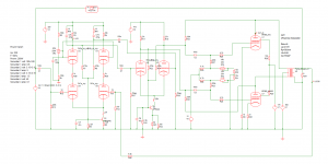
- replaced the input stage with a cascode
- reworked the NFB and the frequency compensation - with great help and tips from Wavebourne Thanks Wavebourne!!!
Result? The amp is more stable. Has wider bandwidth. I'm able to run less NFB with the same THD result.Also, I'm able to exchange the input tubes, without any major modification. Only the biasing of the cascode needs to be adjusted for optimum THD performance.
Tubes I've tried in the cascode: 6N1P, 6N2P, 6N3P (adapter), 6N5P, 6N6P, 6N14P(adapter), 6N15P(adapter), 6N23P, 6N24P(adapter), 6S3Px2(adapter), E88CC... Some of these are sweet-spots THD wise. Won't name them, since the price will go up
Anyway, I can absolutely recommend the cascode for input stage in such amp, where you have one more buffer stage between the input and the power tubes. It's simply very flexible, and tolerates valve inequalities well. Added bonus is the enhanced BW.
The NFB cap is gone - Wavebourne's suggestion. Instead, I've added some dominant pole compensation through the input stage loads. The circuit didn't became too complex. Obviously I had to add an elevated DC heater for the upper tube in the cascode. DC just to remove the hum, to which the cascode is really susceptible. However, now, if you listen very close at the speaker, there is almost no noise at all. There is a very faint hiss, but that's it.
Meanwhile I've done some more experiments:
- replaced the input stage with a cascode
- reworked the NFB and the frequency compensation - with great help and tips from Wavebourne
Thanks Wavebourne!!!Result? The amp is more stable. Has wider bandwidth. I'm able to run less NFB with the same THD result.Also, I'm able to exchange the input tubes, without any major modification. Only the biasing of the cascode needs to be adjusted for optimum THD performance.
Tubes I've tried in the cascode: 6N1P, 6N2P, 6N3P (adapter), 6N5P, 6N6P, 6N14P(adapter), 6N15P(adapter), 6N23P, 6N24P(adapter), 6S3Px2(adapter), E88CC... Some of these are sweet-spots THD wise. Won't name them, since the price will go up
Anyway, I can absolutely recommend the cascode for input stage in such amp, where you have one more buffer stage between the input and the power tubes. It's simply very flexible, and tolerates valve inequalities well. Added bonus is the enhanced BW.
The NFB cap is gone - Wavebourne's suggestion. Instead, I've added some dominant pole compensation through the input stage loads. The circuit didn't became too complex. Obviously I had to add an elevated DC heater for the upper tube in the cascode. DC just to remove the hum, to which the cascode is really susceptible. However, now, if you listen very close at the speaker, there is almost no noise at all. There is a very faint hiss, but that's it.
Attachments
Last edited:
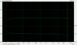
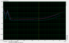
These are the measurements taken at output 23.78V Rms over 8ohm, which is good enough for 70W, for an all-E88CC cascode configuration. Total THD was around 0.17%.
The mess around 30Hz depends on the bias setting of the cascode, which I cannot yet explain why.
At 100W, we're still below 0.8%.
Also he THD distribution seems to be very tube dependent obviously.
Anyway, the amp is so powerful, that you can't turn it up more than 50% for the neighbors going insane. With the reduced NFB it seems to sound more lively, but it's only subjective I guess.
Also, if you take the voltage values, the biasing of the cascode doesn't seem right by textbook calculus, however, these values provided me the least overall THD because of distortion cancellation in the whole amp.
Attachments
Can you do multiple frequencies tests like 2kh + 2.1khz ? ps. I like the schematic a lot.
I guess we can arrange something for that too
ARTA has got an IMD measurement module too. I'll try to do the measurements tonight.As you can imagine, I'm stuck on this design for quite a while now. Unfortunately I've lost the interest lately, since I was not able to enhance more the design. I guess the cascode input stage was the best thing I could find so far. I've tested with different combinations of tubes, 6N3Ps or E88CCs seem to be the best choice, with 6N23P/6N24P very very close in performance.
Ever since (July 2017), I didn't had any new ideas, therefore parked the amp
Now I need that "spark" again, to continue with the experiment... any ideas?
Ever since (July 2017), I didn't had any new ideas, therefore parked the amp
Now I need that "spark" again, to continue with the experiment... any ideas?
Well, the schematic I like, can't change my mind on that.
One thing can be done if, if you want.
The bias on the power tube has no capacitor or something to prevent the bias from turning too low V on a power off sequence or a short power interruption.
It is dependent of the power supply you use of course.
One thing can be done if, if you want.
The bias on the power tube has no capacitor or something to prevent the bias from turning too low V on a power off sequence or a short power interruption.
It is dependent of the power supply you use of course.
- Status
- This old topic is closed. If you want to reopen this topic, contact a moderator using the "Report Post" button.
- Home
- Amplifiers
- Tubes / Valves
- 6P36S push pull HiFi amp