Sweep tube 6P36S PP - measurements inside
Hello all,
I have recently got around 8 pieces of new soviet 6P36S tubes, and would like to build a stereo amp with them.
I'd like something in class AB1, and use ECC81/82/83/85 as driver, since I have got a couple of these.
One of the issues I've encountered was finding some curves for these tubes, to be able to calculate the functional points, and ultimately, to have an idea about what Raa should be used to extract the maximum potential of the tubes, but still with distortion figures which enroll the amp in Hi-Fi class (I intend to use the amplifier at home, for music)")
What would my options be? Can somebody provide a good schematic perhaps?
Thank you!
Hello all,
I have recently got around 8 pieces of new soviet 6P36S tubes, and would like to build a stereo amp with them.
I'd like something in class AB1, and use ECC81/82/83/85 as driver, since I have got a couple of these.
One of the issues I've encountered was finding some curves for these tubes, to be able to calculate the functional points, and ultimately, to have an idea about what Raa should be used to extract the maximum potential of the tubes, but still with distortion figures which enroll the amp in Hi-Fi class (I intend to use the amplifier at home, for music)
What would my options be? Can somebody provide a good schematic perhaps?
Thank you!
Last edited:
6P36S is similar to EL500 (PL500). I have planned to study this type of amplifier in near future too.
I call a stage between phase inverter and output tubes as "driver stage".
You do not need a driver stage for 6P36S.
It can be driven directly from a cathodyne or a LTP-phase inverter.
6P36S is easiest to use as a pentode connected, not UL, because it requires relatively low Ug2.
I call a stage between phase inverter and output tubes as "driver stage".
You do not need a driver stage for 6P36S.
It can be driven directly from a cathodyne or a LTP-phase inverter.
6P36S is easiest to use as a pentode connected, not UL, because it requires relatively low Ug2.
Ri is about 400 ohms, You can use PP OT - about 3 -5 kohm.
http://klausmobile.narod.ru/td/data/_6p36s.GIF
http://sergeev21.narod.ru/pp6p36ssh.gif
http://klausmobile.narod.ru/td/data/_6p36s.GIF
http://sergeev21.narod.ru/pp6p36ssh.gif
6P36S is similar to EL500 (PL500). I have planned to study this type of amplifier in near future too.
I call a stage between phase inverter and output tubes as "driver stage".
You do not need a driver stage for 6P36S.
It can be driven directly from a cathodyne or a LTP-phase inverter.
6P36S is easiest to use as a pentode connected, not UL, because it requires relatively low Ug2.
That is right, I've used the wrong term ("driver"), sorry for that. I'm planning to use a LTP phase inverter.
A question would be what Raa to target for a power range of 30-60W?
A Polish company called INDEL has got some ready made output transformers available for a decent price:
Katalog A
I quicky calculated the conditions with 450 V anode voltage, 170 V as Ug2 and 3k anode load.
The maximum (with optimum components = no loss) output power is some 100 W.
I have earlier built some amplifiers with 6P45S and PL519 and the calculation I made is in good agreement with my actual test results.
The maximum (with optimum components = no loss) output power is some 100 W.
I have earlier built some amplifiers with 6P45S and PL519 and the calculation I made is in good agreement with my actual test results.
??????????? • ?????? ?????
/...."схема усилителя".../ Instead 6Н2П You can use ECC83, 12AX7.
/...."схема усилителя".../ Instead 6Н2П You can use ECC83, 12AX7.
Last edited:
A question would be what Raa to target for a power range of 30-60W?
A Polish company called INDEL has got some ready made output transformers available for a decent price:
Katalog A
I have used Indel TGL40 a lot. It is a 4k to 8 ohms output transformer with UL-taps. It has 4 separate secondaries and very low leakage inductance.
It is built around 180 VA iron and I have used it with very good results at 100 W output power.
It would be very suitable for 60 W as you required. Maybe just some 400 V as +Ub is sufficient to get 60 W.
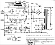
This is the schematic I used with quite similar JJEL509 with 480 V +UB and 130 V as Ug2.
An externally hosted image should be here but it was not working when we last tested it.
Last edited:
I have used Indel TGL40 a lot. It is a 4k to 8 ohms output transformer with UL-taps. It has 4 separate secondaries and very low leakage inductance.
It is built around 180 VA iron and I have used it with very good results at 100 W output power.
It would be very suitable for 60 W as you required. Maybe just some 400 V as +Ub is sufficient to get 60 W.
This is the schematic I used with quite similar JJEL509 with 480 V +UB and 130 V as Ug2.
Thank you for the suggestion!
I was looking at the TGL40-001 myself a while ago, and was impressed by the size of the core, which is absolutely huge!
The schematic of Artosalo is suitable for direct coupling prestages without interstage cap /that will be better for sounding/, if You will adjust the mode of phase splitter /in Your place I will do it.../
That would be a good idea too! Good coupling caps are a bit more expensive, and introduce phase rotation. I need to study this option, something tells me that this would be the way to go.
Do you mean C22 ?
I don't comment about the sound at all, because it is fully subjective and definitely varies according to listener.
Technically speaking, it is preferable the optimize both, voltage amplifier and phase splitter separately. If these stages are dc-connected, this possibility is lost.
Typically the optimum operating point of voltage amplifying stage is such that the anode voltage is higher than the optimum grid voltage of the cathodyne.
Therefore dc-connection is a compromise.
I have studied this subject a lot and know how it is.
In such case when the drive voltage of the output tubes is low the dc-connection can work well. For example with pentode connected EL84 PP amplifier.
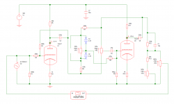
A while ago, with the help of a friend we designed the following schematic, for a pair of 6P3S-E's. This never got built, since I moved away from these tubes to some more potent ones, like the sweep tubes (which can provide more power in peaks - which is just about right for music listening).
Anyway, I liked the input stage and the phase splitter on this one, lookie here:

Anyway, I liked the input stage and the phase splitter on this one, lookie here:
6F12P is good, but not very good choice.Do you mean C22
Typically the optimum operating point of voltage amplifying stage is such that the anode voltage is higher than the optimum grid voltage of the cathodyne.
Therefore dc-connection is a compromise.
I have studied this subject a lot and know how it is.
amplifier.
In more cases with quality tubes cathodyne has 80-100-120 and more V.
But if I use pretube /6SN7, ECC88, 6N23P....more 10-20 kinds/ with low plate voltage /about 80 - 120V/?.......
I think every inter stage cap is little "evil".
And I built myself SE with parts and modes that I like.
My moto is - "Ni-End is back proportional to the number of composite parts"....
Last edited:
Well, it is a bit off-topic to begin discussing if 6F12P is good or not very good, but why not ?
At first I'd like to know what you mean with "good tube".
Is it something concrete and something that can be measured and observed ?
It is a fact, not an opinion, that 6F12P is a good tube.
It has a very linear hi-mu (100) triode which also has very high transconductance (19 mA/V). So the triode section can provide high gain, but also low Rp.
I can be used practically in all sort of voltage amplifiers, phase inverters etc. with excellent measurable performance.
The pentode section is also having the same high transconductance (19 mA/V) and is very linear too.
The maximum anode dissipation of the pentode is 5 W. So in addition to all above mentioned applications, it is possible to build a small output stage with this pentode too.
I think that 6F12P is one of the latest and most advanced tube construction that was developed during tube era.
OK, Artosalo, You like it and for You it's very good tube, but if hundred DIYers tells the same, I will believe You. I saw it data, ....good tube and no more, very good data doesn't mean in more cases very good sound, that good sound I'm waiting to hear from a lot of DIYers..../You like sound of triode with mu 100....I don't like sound of the same with very good data....everyone has own opinion....the discussing isn't necessаry...sorry for bad English /.
Last edited:
I have an SE amplifier with triode-connected output stage and without GNFB.
Once one of my friends who is a "heavy class" HiFi-man and diyer listened it with me.
He liked the sound of this amp a lot, actually so much, that he insisted me to give the schematic.
Then at same evening he begun to build this amplifier, because it had so great sound.
An other of my serious HIFI-friends tested this same amplifier for a couple of weeks.
His estimation was complete opposite. He told me that this was one of the worst sounding amplifier he had used.
So, what is good sound to one person can be bad sound to an other.
Therefore I classify tubes, amplifiers etc. according to their real, measurable performance. These features do not depend on any person and his taste.
These features are facts, not opinions.
OK guys, please don't start a "war" here regarding which is the better sounding tube
Everybody is entitled to have his/her own opinion regarding a certain topic.
In any case, what I really wanted with this thread was to find a couple of answers about the directions I should take with what parts I've got at my disposal, and so far, so good.
I didn't mention, that I'm planning to use a couple of SMPS's for the heating circuit and for the HT.
SMPS because they're lightweight, and efficient. The transformer I've got is quite big, around 15 kilos! Add to that two TGL40's, 3kilo each.
Separate supplies, as if I decide to change the tube, it's easier to change the heating voltage (go from 6.3V to 27 for example, for the PL tubes).
Hello all,
I have recently got around 8 pieces of new soviet 6P36S tubes, and would like to build a stereo amp with them.
I'd like something in class AB1, and use ECC81/82/83/85 as driver, since I have got a couple of these.
One of the issues I've encountered was finding some curves for these tubes, to be able to calculate the functional points, and ultimately, to have an idea about what Raa should be used to extract the maximum potential of the tubes, but still with distortion figures which enroll the amp in Hi-Fi class (I intend to use the amplifier at home, for music)
What would my options be? Can somebody provide a good schematic perhaps?
Thank you!
A good diagram that will not fail safe, EL500 (EL504) are equivalent 6P36S can set the 6P36S are even stronger and better than EL500 (EL504) ...
Attachments
I'm getting back with some updates on this project...
After some careful considerations, I'll stop the SMPS building over here, since the exact required voltages are still not clear.
However, I've got a big transformer from a previous project (at least 500W or so, judging from the size of the core), with two anode voltage windings of 476V, each with taps at 173V. There are two 33V windings, these should be good for the bias of G1.
For initial test, I'll use this.
I'm intending to set up the 300V winding for the B+. This is supposed to yield around of 430V after rectifying and filtering.
Then, use the 173V for the G2 voltage.
I believe that this setup should be flexible enough to experiment the exact functional points of the amp.
Combining this with some TGL40's, this should yield an interestitng setup.
Artosalo helped me with some information about how to draw the load lines for the output stage. Have to thank to him!
My single concern is that I don't really have access to an oscilloscope, so I will not be able to get an idea about the distortion figures...
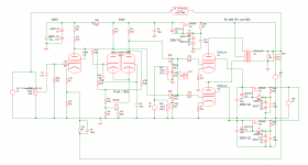
So here it is, more or less the final iteration for this amp I am experimenting since a while now.
Special thanks go to my friend and fellow forum user, Artosalo, for providing me with lots of great advices to achieve this design! Thank you, Artosalo!
It's a PP based on a pair of 6P36S, LTP phase splitter with 6N1P-VI and EF806S as input device. It's supposed to be around 75W or so in this configuration, I was not able to do any more in-depth measurements, as I don't have an oscilloscope. Anyways, I'm pleased with the result, it sounds pretty strong even so.
The OPT is an INDEL TGL40/001, 4k-to-8ohm part. Cheap and good.
The input stage is DC coupled with the LTP. The latter uses a sort-of bias servo with mosfet, inspired from the PL519 KaizerPower amp (and others), seen here, on this forum. This allows to automatically balance the splitter, without needing different anode loads. I've found that around 100V on the input grid of the LTP is a
The power supplies around the amp are all stabilized, perhaps a bit over-engineered. G2 is ast 205V, which was found to be optimum for this tube distortion and power output-wise. The tubes sit at around 38mA at idle each, this can be increased until 46mA, depending upon preference, and further study.
I've got a tone control hooked up at the input, it's Artosalo's design, with a couple of modifications for the tube and my personal preference for the sound of it. This is with ECC83's I've got lying around, unused.
Please comment on this!
Attachments
Last edited:
- Status
- This old topic is closed. If you want to reopen this topic, contact a moderator using the "Report Post" button.
- Home
- Amplifiers
- Tubes / Valves
- 6P36S push pull HiFi amp