I am fully aware that this is considered to be sacrilege by many, but I myself am not afraid to utilize solid-state devices with tubes. In my eyes, a lot of the best solutions utilize the best of both worlds.
For me, it's just an experiment.
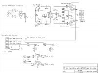
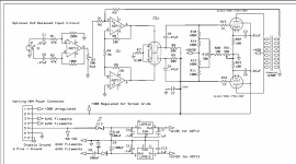
So here's the design. I only used the AD713 because 1) I have them, and 2) LTSpice has this particular Analog Devices chip in its default library. I may switch this out for an OPA2604.
The Balanced input is not necessary and somewhat redundant, but I like to use XLR connectors for my amplifiers because it's a great connector.
The challenging limitation here is the fact that I am limited to a 6-pin Harting connector connecting the PSU chassis to the amp chassis. It also has a dedicated ground pin. This will likely be tested in my PP 1625 amp, as there's a fair bit of space in the chassis for a test board. Due to the pin limitation on the connector, I'm hoping I can run the Op-Amps off of the bias supply. The transformer is more than large enough, so no worries on that, but obviously I don't have enough pins to run a dual rail supply. So this is what I came up with for a rail splitting device, not sure if it's the best way.
The negative feedback circuit has not been worked out yet, if anyone has suggestions on where to connect it, please share. My experience with op-amp design is pretty minimal, so there may be some glaring issues. That said, the Spice model looks good, but obviously LTspice != Reality. However, I do believe that this could be very easily adapted to work with a huge variety of tubes from 6V6s (or smaller) all the way up to big sweep tubes and KT88s.
Also, the schematic does not show all the correct resistor values for the bias supply.
For me, it's just an experiment.
So here's the design. I only used the AD713 because 1) I have them, and 2) LTSpice has this particular Analog Devices chip in its default library. I may switch this out for an OPA2604.
The Balanced input is not necessary and somewhat redundant, but I like to use XLR connectors for my amplifiers because it's a great connector.
The challenging limitation here is the fact that I am limited to a 6-pin Harting connector connecting the PSU chassis to the amp chassis. It also has a dedicated ground pin. This will likely be tested in my PP 1625 amp, as there's a fair bit of space in the chassis for a test board. Due to the pin limitation on the connector, I'm hoping I can run the Op-Amps off of the bias supply. The transformer is more than large enough, so no worries on that, but obviously I don't have enough pins to run a dual rail supply. So this is what I came up with for a rail splitting device, not sure if it's the best way.
The negative feedback circuit has not been worked out yet, if anyone has suggestions on where to connect it, please share. My experience with op-amp design is pretty minimal, so there may be some glaring issues. That said, the Spice model looks good, but obviously LTspice != Reality. However, I do believe that this could be very easily adapted to work with a huge variety of tubes from 6V6s (or smaller) all the way up to big sweep tubes and KT88s.
Also, the schematic does not show all the correct resistor values for the bias supply.
Attachments
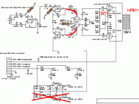
I believe that some DC path for the first opamp's inputs needs to be in place. Any DC on pin 6 will affect the phase inverter chips. That will vary with the volume control setting.
There definitely needs to be a DC path to a fixed voltage source for the 6SN7 grids. If you have a negative voltage source tied to the CCS on the cathode instead of ground, then the grids can be grounded through a high valued resistor, 220 K to 1 meg. The -15 volt supply for the opamps is suffient for most CCS chips. The -68 volt supply will work for the 10M45. If the CCS is indeed grounded, there should be a small positive voltage on the grids for the CCS to have sufficient headroom to function properly under large signal conditions.
The standard 7918 chips can't eat 68 volts, most are 30 to 35 volts maximum. A positive regulator chip like the 7818 will not work with a negative voltage on it's input. Smoke or dead parts happen.
Yeah, looking back on the schematic I see a few of the issues you mentioned. In theory, any issues now are design related, not drawing related. The power rail splitting thing I was trying to show before is now drawn the way I mean to draw it. Blocking capacitor between the first op-amp and the second is now in place (forgot about that... probably a smart thing to do). 10M45 is now tied to -68V, and the 6SN7 grids are grounded through a 1 Meg resistor. The regulators are still dropping a little more voltage than I'd really like, so I may insert a dropping resistor in there beforehand.
Attachments
You left the driver as a tube. That's the most important place where SS wins over tubes.
I would also tend to agree. you need some voltage gain between the opamp and the output tube, and a 6SN7 is a good choice, but the best parts to directly feed the grids of the output tubes are mosfets.
The 6CG7 is a shrunken 6SN7, so look at the second stage and mosfet drivers in this design. Copy whatever you want from it.
Tubelab Universal Driver Board, 2015 version
Hopefully this week I'll have time to play around with models for a source-follower for the driver portion just to see what it looks like.
Am I correct that the reason a FET is a better driver than a 6SN7 is because they can supply current if the grid of the output tube is driven positive? That was on my mind as I was drawing this, but I ultimately concluded that it's still probably about as capable in this regard as a tube-based LTP driving the outputs, just with a (theoretically) more closely balanced phase inverter.
If I have time (and if it ever stops raining long enough for the basement to dry up) I may try breadboarding up this current design, just to see how it performs. I can also try some source followers at that point.
Why do you think you have a better balanced PI with that design?
Your input stage doesn't make sense by the way. The AD713 is a regular opamp, so the non-inverting and inverting inputs have very different input impedances. It's not the way to implement a balanced input with opamps.
Your input stage doesn't make sense by the way. The AD713 is a regular opamp, so the non-inverting and inverting inputs have very different input impedances. It's not the way to implement a balanced input with opamps.
I built a signal generator for bench testing tube stages using an ADA4700 and two cheap 48V switching supplies to provide the rails. The distortion it produces is so much less than a 6SN7 at comparable levels it is ridiculous, and it is low-order as well. I can't detect anything over 3rd harmonic at any level all the way up to 30Vrms. There is nothing wrong with using op amps if done right.
I wanted to kill the ground loop sounds in my KT88 Unity-Coupled amp permanently and was looking at adding input transformers. The only trouble was the space constraints wouldn't allow it, so I replaced the 6SN7 input stage with input transformers and an ADA4700 input stage (in the configuration of the input stage of an instrumentation amp). Transformers sit where the tubes used to and the amp is dead quiet.
You could probably choose a much better op amp for audio and you definitely need to add DC references at various points like has been mentioned. I'd use LM4562 wherever levels are low and ADA4700 where you need to swing some volts. If you really want some good ideas, get Douglas Self's Small Signal Audio Design book for best circuits for all of the low-level stuff.
SS ph. inv. will cause SS sound. How do You like?
Me? I love the lack of ground loop buzz, but I have the input transformers to thank for that. Otherwise, I can't say that I notice any difference...
The 6SN7 had very low distortion and the op amp had astonishingly low distortion. It's hard to tell the difference between the two input stages when the DHT driver stage (841) is by far the dominant source of distortion in the amp.
SS ph. inv. will cause SS sound.
A correctly implemented SS phase inverter should not affect the sound if it is compared to a tube inverter where neither are operated outside their linear regions since as stated neither should be anywhere close to being the dominant source of distortion or sound coloration. This is not always true in a guitar amp operated well into the distortion region. I have NOT experimented with opamp phase inverters in a tube amp, so I don't have hard experience here. I have used mosfet phase inverters in tube amps. A correctly implemented split load PI with EQUAL load impedances under ALL operating conditions should impart no sound whether it uses a tube of a mosfet. A BJT could impart some imbalance due to it's base current.
Am I correct that the reason a FET is a better driver than a 6SN7 is because they can supply current if the grid of the output tube is driven positive?
A follower, tube or mosfet, directly feeding the grid of the output tube eliminates the coupling cap tied directly to the grid and the possible bias shift that can come with transient signals. The main parameter in selecting the proper component for a follower in Gm. It's hard to find a tube that comes close to the Gm in even the cheapest mosfet. The high input impedance of a follower helps guarantee equal loads on the two terminals of the phase inverter. For more info read this:
Power Drive | Tubelab
If You cant notice the difference. why You need tube end amp....SS end amp is very cheaper. /The goal of tube audiophills is pure tube sound..../.Me? I love the lack of ground loop buzz, but I have the input transformers to thank for that. Otherwise, I can't say that I notice any difference...
The 6SN7 had very low distortion and the op amp had astonishingly low distortion. It's hard to tell the difference between the two input stages when the DHT driver stage (841) is by far the dominant source of distortion in the amp.
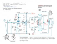
The "balanced" input *needs* the 4th resistor.
While this form of balun has impedance quirks, it is studio-standard and plenty good for domestic use.
If you cap out of the gain pot you *must* gives a DC reference to the next opamp.
If both opamps are biased near zero, you do not need an R-C into the tube.
Since the two triodes are driven balanced, and a large negative supply is available, the CCS can be a simple resistor with negligible lack of balance (less than tube-matching).
The power stage bias: you start with -68V, cut that at least in half R16 R18, then cut it again by factor 21 with R14 R12. 1.6V on 6L6 G1 will not do! (The "3V" was a hasty count.) Also both the bias-adjust and bias-balance allows you to trim 6L6 bias to ZERO. Never let the tech do that!
I do not understand the +/-18V supply. I may be dazed by its brilliance, but I suspect it does not work like you think. (Here I would not trust a simulator as much as a matchbook sketch.)
Naked pentodes to a speaker is nasty sound. You want to plan for NFB.
No idea what 0.01uFd on 6L6 G2s does for you. They will do nothing until like 2KHz.
Attachments
+1. Just disconnect the NFB from a pentode amplifier and let us know what you think!Naked pentodes to a speaker is nasty sound. You want to plan for NFB.

I do not understand the +/-18V supply. I may be dazed by its brilliance, but I suspect it does not work like you think. (Here I would not trust a simulator as much as a matchbook sketch.)
Thanks for the suggestions, is there a better way for me to get the positive and negative voltage supplies needed for the op-amps? As I mentioned, the 6-pin connector is a bit more of a limitation than I anticipated.
None of the resistor values in the bias circuit are correct, they are just filler values in the schematic as I haven't had time to sit down and properly calculate them. That will be done, not to worry.
When I have a chance I think I'm going to model a cathodyne phase inverter with MOSFET source followers, just to see what it looks like.
I think it's pretty obvious that my electrical engineering skills are still fairly early in the learning curve, but I really do appreciate the feedback on my design.
Also, I personally feel that both SS and tube technology can make excellent sounding amps. I also feel that there's crappy designs and crappy executions of designs in both areas. If I end up with a tube amp that "sounds like a solid state amp", that isn't necessarily a bad thing. I like the sound of my MC^2 MC650, and the sound of my Heathkit AA-121.
Also, I will indeed implement feedback, but I haven't yet worked out exactly how I want to go about it.
If You cant notice the difference. why You need tube end amp....SS end amp is very cheaper. /The goal of tube audiophills is pure tube sound..../.
Speak for yourself and your own goals. I don't need dogma. Besides, pure tube sound doesn't exist on any modern music. It has been through dozens of solid-state stages on its journey from original sound wave to the sound waves coming out of your drivers. I still enjoy my tube amp with op amps.
H713,
I have used "Meanwell" brand isolated-output switching supplies to power op amps. I bought two 48V supplies for my ADA4700 stage and just stacked one output on top of the other, connecting the center to ground and fed AC into the inputs. Super easy.
I think it's pretty obvious that my electrical engineering skills are still fairly early in the learning curve, but I really do appreciate the feedback on my design.
I can't recommend Douglas Self's book enough if you are a beginner with op amps and audio.
Why does a DIYer use tubes? There are several answers. Mine are pragmatic: simplicity and superior performance in specific roles. Frequently, a combination of tubes and SS will do a better job than either technology alone. JMO, the sonic results are what matters. I'd use a lump of galena, if it yielded good sound.
The 6Y6 project I worked on with Jeff Yourison would not have been possible, without the MOSFET "concertina" phase splitter. Even then, things were "touch & go", given B+ rail restrictions. No triode I am aware of can swing as close to the B+ rail as a MOSFET.
The 6Y6 project I worked on with Jeff Yourison would not have been possible, without the MOSFET "concertina" phase splitter. Even then, things were "touch & go", given B+ rail restrictions. No triode I am aware of can swing as close to the B+ rail as a MOSFET.
Attachments
An other way to do the supply. No need for a long tail on the 6SN7, the IC is the PI. Bias circuit bad trimpot resistant (no loss of neg volt).Thanks for the suggestions, is there a better way for me to get the positive and negative voltage supplies needed for the op-amps? As I mentioned, the 6-pin connector is a bit more of a limitation than I anticipated. <snip>
Mona
Attachments
- Status
- This old topic is closed. If you want to reopen this topic, contact a moderator using the "Report Post" button.
- Home
- Amplifiers
- Tubes / Valves
- 6L6GC PP amplifier with SS phase inverter