No, the grid at pin 7 has no grid leak resistor. The one fed by two (?) capacitors and a resistor.
It has a 1 Meg to the input jack ground on The first tube. ? The one that has a 471 pf blue Cap also. That is Stage two of tube 1.
Actually I have the other side going to positive from the grid rather than negative and I need to switch that one. The other one on pin 7 is okay.
I fixed the grid resistor and I made sure that it was still working afterwards and it is. I'm surprised that it even played At all with a 1 Meg grid Resistor on the inputs positive. On doing The Negative Feedback Resistor the Blues DeVille design uses 68k and on the Sovtek 50 uses 56k plus a 4.7 K to ground and A bypass pot of 4.7k . It seems like they are about the same resistance between 64k and 68k on Their negative feedback loops. It's called a presence pot on the Sovtek. Should I get a 5k pot and use a 56k and 4.7 to ground like on the Sovtek 50 for my Negative Feedback ? I don't have any normal 5k pots but I can get one. I have two 5k Bias pots but I am assuming that they are using it on the front as a presence adjustment. Will I even notice 5k of Negative Feedback adjustment ?
Last edited:
It's a S-100 4 ohm Compact Monitor, University Sound. No nothing about it borrowing it for testing. Says 160 watts nominal impedance 4 Ohms. My plan was to get a Peavy 8 ohm 12 inch for it.
Hard to know what you're talking about when you don't post updated schematics, but leading from pin 1 of the first valve to pin 7 of the 2nd valve you have 0.22uF in series with 100k in series with 470pF, and pin 7 should now be shunted by 1M to ground..
My question now is why the 100k+470pF? This constitutes a high shelf filter with Ft around 300Hz. It's cutting out most of the music. Remove the 100k and 470pF.
If the 100k resistor is meant to be a grid stopper it is (a) in the wrong position and (b) at least 10x too large. It should be 1k to 10k attached directly to pin 7 as close as you can get.
The point of the 470pF capacitor escapes me completely.
It's got way too much gain is what I was trying to say. Adding NFB didn't help it any. What did help was changing the cathode resistance from 1.5k to 10k on stages 2 and 3 and reducing the bypass resistance on those two Cathodes to 1 uf from 22 uf. , I can turn up the volume past 1 now and it is still loud but it is not super distorted anymore. It's late now and I can't play it loud right now so I will have to wait until tomorrow to do anymore. I need to read the posts again tomorrow and think about what you are saying. I'm a little bit rusty because I have not built any amps for a few years now. And dealing with the higher gain tubes like 12ax7 is pretty New to me. I usually just repaired them if they had a issue. I have not tried to tune any 12AX7 tubes before.
EJp , I was just following the Blue's DeVille design for the most part on the pre Amp. I will create a updated wiring diagram for it tomorrow with the changes that I made. You may be right with what you are saying. I'm still learning it's the first 12AX7 and 6l6 that I have built from scratch. I was just trying to use known working diagrams. It did work but it was not right. I couldn't get all of the exact part's for everything and That is probably why it has given me the trouble. I'm not trying to shift the blame on the diagrams that I used. I will try to include the complete design of what I built this time. I might try to add the NFB again now that it is working better.
NWhat NFB? You have MFB from unbypassed cathode resistors, but you can’t have NFB around a passive tone control.

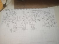
Here's a complete wiring diagram from The input to the 6l6 tubes with the voltages. I figured out that I cant use any negative feedback on this type of design. After changing the cathode resistance from 1.5k to 10k and the bypass resistance to 1uf from 22uf it sounds a lot better than it did before. I have a problem with the treble being too much - I have to turn it almost all the way off on my guitar or it gets hissey sounding. The Bass and mids both sound pretty good. The two 6l6 GC Are running At 75ma each At idle.
Attachments
Last edited:
My wall voltage is 122 vac. I know that 75 ma's is a lot At idle for 6l6GC about 106% but I have heard that you can do it with them safely and that some people do it all the time with guitar amps. I'm not sure ? They are getting pretty hot but they don't sound bad or like it is hurting them.
You have a problem with the treble being too much because of your crazy RC coupling between the first two stages. You've changed the values but you haven't eliminated the problem. Nor have you explained what it is for. You still have an HP filter. Why? Remove the 150pF capacitor and you will get your bandwidth back.I have a problem with the treble being too much
And please show where the earth connections are in your tone control pots. You need to ditringish between a 'wiring diagram' and a schematic. This here is neither.
I decided to raise up the Bias voltage to negative 45 from negative 25 to slow down the idle ma's. I changed the 15k resistance to 6.8 K , It is 20/20 At idle Now from 75/75. I have two separate 5k bias pots that I was thinking about hooking up so I can adjust it some more without changing the resistor's or the big resistor. My voltages have All risen up now. Plates are 488/486 , Screen's Are 422/422 , -45/-45 G1, 20/20 ma's on the 6l6 GC tubes. The Phrase Inverter 12AT7 is 158/160 on The Plates and 21 volts on the cathodes. The second 12AX7 is 1/2 being Used with 228 on The Plate , Tube 1 is a 12AX7 with 222/221 Plates. It seems to sound pretty good now and the 6l6 tubes are both running cooler. The Bass and mids are good but I think that The Highs are a little bit compressed but it's not real bad just a little bit. I was wondering if adding the two Bias pots and lowering the negative voltage down a little bit for higher idle ma's than The 20/20 would help with the sound of the highs Any ? . Up at 75/75 idle with 420 volts on the Plates , -20/-20 on G1's , And 355/355 on the screen grid's the Highs were too much for me. It seems like the voltage and ma's are affecting the Highs more than anything else. What I am thinking is that you have to tune the tubes with the negative Bias Voltages to get the tubes to balance out between the highs and the lows. And afterwards I could do something with the tone stack or Preamp tube section to make it even better sounding. I'm not using great power tubes they are JJ tubes. They actually sound a lot better in this amplifier than they did in my fender Hot Rod DeVille. I took them out of the fender because they didn't sound good in it. It sounds better than I was expecting from The JJ tubes to be honest. I was wondering if the Caps I used on The Bass and treble pot's are the best size's also ? . I'm using A 4 Ohm speaker for testing and I was wondering if the speaker is killing off some of the highs also ? . I know that It has a 8 Ohm Output Transformer. Can I connect two 4 Ohms together positive to negative and will it be the same as using a 8 Ohm speaker ? I'm thinking that maybe it is The 4 ohm speaker messing with the Highs. I know that they use A 3.2 Ohm speaker in The old champ's and the Highs still sounded good. But they are not push pull amps. I'm looking for a balanced sound from top to bottom. Like every other guitar player All I want is perfection from my amplifier. It's getting better and better as I have been messing with it. I've been listening to the post suggestions and Then doing research on them. Right now I am thinking about the speaker ohm's and adding the bias pots.
Ejp, If I do what you said and remove the 150 pf tone cap I lose almost all of the volume of the amplifier. Maybe it would be better to just slightly lower the Cap sizes on the Bass pot instead. I put it back how it was before and I was playing the amplifier with a guitar and I think that the bass might be actually more of a problem than the treble is. And maybe it is just because I am using A 4 Ohm speaker on a 8 Ohm Output Transformer. I haven't bought a speaker for it yet and I borrowed one for testing. I had a similar problem once with a Rockola Jukebox having too much bass with a tube amplifier and I cut in half the size of the capacitor on the volume control and it fixed the problem with having way too much bass. I didn't have a Bass pot on the jukebox but I think that the principal would still apply with the capacitor controlling the amount of bass. Or I could up the 150pf to 250 pf instead. I think that Either way would probably work.
Last edited:
I'm pretty much done with it at this point. I paralleled Two 150 pf and it came out 250 pf when I tested it and that was what it called for on the tone pot. I like the way it sounds and plays now. Thanks for the help and input. I'm On to making The Amplifier cabinet and A separate speaker cabinet for two 12 inch speakers.
By 'remove' I mean short-circuit it, of course. If you just remove it nothing will come out at all.If I do what you said and remove the 150 pf tone cap I lose almost all of the volume of the amplifier.
You still haven't told us what this capacitor is for.
- Home
- Live Sound
- Instruments and Amps
- 6L6GC mono Amp together but it's not loud?