Hi,
I have a Palcom TA-70 tube amp (same as Dynavox VR70) that I have been modding. Replaced all caps with high end ones, nice NOS RCA pre amp tubes. This amp uses 4 EL34's and there is enough bias range for 6L6GC tubes. Can I just put them in with a rebias or do I need to change more to be able to safely use 6L6GC's?
I have a nice quad of RCA blackplate 6L6GC's that I would like to use 🙂
It won't be optimum, but it won't blow up. The 6L6 series works better with a somewhat higher plate load impedance and requires a higher voltage drive compared to EL34.
Thanks, I just put them in and they sound nice. The amp seems a bit louder at the same volume setting.
If there are modifications that can be made to optimize the amp for 6L6 i'd like to make them , so any help is appriciated.
I would set the bias to read;
Anode dissipation, say 25Watt, divided by the HT multiplied by 0,707 is the dissipation of the valve including the screen grid. The screen grid uses about 5% of the anode value.
So for a warm class A 27 Watt bias, set the voltage drop across the 10R cathode resistor to (27/420X0.707) 45mA = 450mV
For a cooler running Class Ab use 17/420X0.707 = 28mA = 280mV
The 6L6GCW or 5881 is on a par with the KT88. The best valve designed for high power audio.
I prefer around 35mA
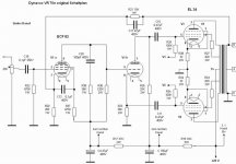
This is very similar to the Dyna design. The phase splitter in this case is unbalanced, which is not a good design practice- you want anode and cathode resistors to be matched and equal. Even then, the drive voltage requirement for the 6L6GC will be straining things a bit, but you could probably get away with it. You'll want to adjust the compensation and lead cap for stability and bandwidth to accommodate the new tubes.
It biased at 42Ma right now..
SY:
On the schematic, which parts should be changed to what values? Thanks!
SY:
On the schematic, which parts should be changed to what values? Thanks!
R35 should be 36k and matched to the cathode resistor (buy several dozen 36k resistors and find a pair that match as perfectly as possible, absolute value isn't critical). If your output tubes are decently matched, you'll get a significant decrease in distortion.
C17, C20, and R38 should be adjusted. This will have to be done experimentally using a square wave and dummy load. You want to minimize ringing while not killing the rise time, and then confirm stability by placing a few different values of capacitors (from about 0.5 to 5uF) across the dummy load.
C17, C20, and R38 should be adjusted. This will have to be done experimentally using a square wave and dummy load. You want to minimize ringing while not killing the rise time, and then confirm stability by placing a few different values of capacitors (from about 0.5 to 5uF) across the dummy load.
Yes. And yes, you need a scope and generator. If you want to modify auto engines, you need a set of wrenches. 😀
Not much, really. Lower will increase the standing current in the phase splitter, higher will increase it. I wouldn't go too far off, though- it won't matter if it's 33k or 36k, but it will matter if it's 100k or 10k.
Changed the 200Ohm screen grid resistors which seemed kinda low for an ultra linear design to 1k. Should be less hard on the tubes.
- Status
- Not open for further replies.
- Home
- Amplifiers
- Tubes / Valves
- 6L6GC instead of EL34