The original engineer's schematic did not show Ultra Linear Taps.
If there are no UL Taps, live with lower power out . . .
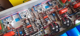
Triode Wired Parallel Push Pull 6L6GC.
If there are no UL Taps, live with lower power out . . .
Triode Wired Parallel Push Pull 6L6GC.
Guys, this was the last design of Johan Potgieter, a member here, and a very talented one. Since his son made the request I believe the appropriate thing to do is to finish the amplifier as close as possible to as designed out of respect for the father who did not live to see his project to fruition, and the son who would probably want the amplifier his father designed and not something else.
I remember him talking about this design at some point in the past.
It appears to be a solid design, and I dare say the problem with latching the B+ off under a fault can probably be solved with some relatively basic design changes to the protection circuits.
I remember him talking about this design at some point in the past.
It appears to be a solid design, and I dare say the problem with latching the B+ off under a fault can probably be solved with some relatively basic design changes to the protection circuits.
Last edited:

I don't see 100 watts coming out of a pair of 6L6's. 40 to 50 watts I can see from a pair of them.6L6 Power Amplifier - A grandmasters unfinished dream
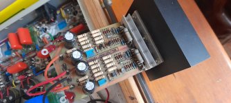
I have been approached by the son of a local electronics engineer who passed away last year. He was still working on his ultimate valve power amplifier system.
All the parts and schematics were collected and I am now trying to make sense of it all. It is a difficult task to take on since the man who designed it is not available anymore for any comments.
The amplifier is quite elaborate. 100 watt per channel, servo bias control, overload protection as well as grid drift compensation and cathode windings in the output transformer.
In the notes the man stated that he battled with the overload that reset itself after a short while - he wanted it to stay latched when it tripped. Also, there is a spike pulse on the 500 vdc regulator.
If any member here is keen to cast an eye on the schematics, I would be very grateful.
1. Unfinished schematics of a person who passed away do not have to be correct; and they do not have to show anything.
The schematic of Post # 1 is clearly marked: 4 x 6L6 GC.
All 6 connections of the 6L6GC, except the filaments are shown.
It does show a solid state bias circuit; but since Push parallel 6L6GC are connected to one cathode winding, and Pull parallel 6L6GC are connected to one cathode winding, that requires very well matched pair for Push, and very well matched pair for Pull.
Build your own amplifier however you want it.
Last edited:
I meant to say that I wish it was a simple to redesign and make new PCBs etc but I dont know who is going to fund it. Aint happening gratis.It is.
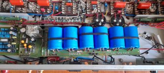

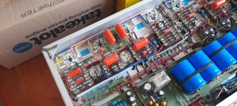
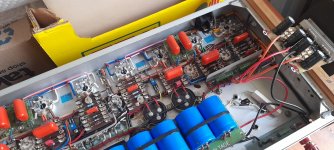
It is a joy to behold! Design meets technical prowess meets art.
What you have is an early prototype. The hard part is to assess how close it is to being anything other than a prototype.
If this was an IT system with issues, the going backwards in order to go forwards solution would be to isolate the separate subsystems and test them within expected operating conditions independently. That means creating tools to set the different parameters for operation, and simulate the different failure cases. Then those assumptions about conditions might end up being challenged when it was operating again as a system, but then the test frameworks have already been created and can be tweaked and be used to iron out the operating problems.
The design is modular, and the requirements are straightforward, so it should be solvable.
It is a joy to behold! Design meets technical prowess meets art.
What you have is an early prototype. The hard part is to assess how close it is to being anything other than a prototype.
If this was an IT system with issues, the going backwards in order to go forwards solution would be to isolate the separate subsystems and test them within expected operating conditions independently. That means creating tools to set the different parameters for operation, and simulate the different failure cases. Then those assumptions about conditions might end up being challenged when it was operating again as a system, but then the test frameworks have already been created and can be tweaked and be used to iron out the operating problems.
The design is modular, and the requirements are straightforward, so it should be solvable.
Solvable perhaps , but by no means easy . @deltavektor is quite experience with audio design , over the years he has designed and repaired both studio and hifi gear . Even so , the old man Johan was highly regarded for his design ability , even more so for his knowledge of the intricacies of electronics in general , so @deltavector (Dewald) is asking for help directly . Problems he has detected listed below .
The amplifier is quite elaborate. 100 watt per channel, servo bias control, overload protection as well as grid drift compensation and cathode windings in the output transformer.
In the notes the man stated that he battled with the overload that reset itself after a short while - he wanted it to stay latched when it tripped. Also, there is a spike pulse on the 500 vdc regulator.
If any member here is keen to cast an eye on the schematics, I would be very grateful.
6L6GC Maximum quiescent voltage:
500V plate to cathode
450V screen to cathode
If the plate B+ is 600V, and the screen B+ is 500V,
Then we need lots of DCR in the plate/screen windings, and lots of DCR in the cathode windings.
Without lots of DCR, those protection circuits are going to be needed, because we may have thermal run-away.
Or, we simply adjust the B+ voltages as needed.
And, we do not know how much cathode current the bias circuit runs the tubes at.
Cathode current x 'cathode to plate voltage' is the approximate power dissipation total of the plate and screen.
Watch that number, versus the 6L6GC max dissipation specification.
It still would be a very good idea to do some measurements of the DCRs of the plate windings and cathode windings.
(hint: be sure to short together all the secondary taps: common, 4, 8, 16, whatever. That way, an Auto-ranging Ohmmeter is not going to go crazy trying to find the right range, so it might not settle on a range, because of the primary winding inductances, and you get an incorrect reading of DCR).
(Ask me how I know that).
Last edited:
Yes it is terribly high600V on the anodes of 6L6GC seems terribly high . What do you think ?
Perhaps this should be kept in its original condition, taking a museum-like approach. Something like this falls outside of the Ka-Ching! realm of owning a priceless (but still salable!) artifact and approaches the realm of an important art piece not yet recognized. Like an early computer, or other modern (increasingly invisible, because not "digital") technology.
Not especially crazy about the circuitry, but as a piece of art, it's worth preservation,
All good fortune,
Chris
Not especially crazy about the circuitry, but as a piece of art, it's worth preservation,
All good fortune,
Chris
The 360V rating on original metal 6L6 was about the pin-base, not the insides. The near-twin 807 had much higher ratings because top-cap. The 6L6GC is really a TV H-Sweep tube, the 6BG6, an upgraded 807-type rated 700V, moved from top-cap to all connections on base the way audio amps normally do it.600V on the anodes of 6L6GC seems terribly high
I have no doubt that 1966 RCA/GE 6L6GC in excellent sockets in clean air would survive 600V. This extreme may even be mentioned in GE Notes for ham radio (where you don't transmit for thousands of hours). We also note that original EL34 ratings said 800V which does sound awful bold.
There's also 6550/KT88 which will take 600V for decades (check heater load).
I agree this may be an on-going experiment and the lead investigator is gone.
Hi @PRR ,
I kind of half knew the story about the inter-relation of the 807 and 6L6GC , but understand a little bit better now .
I hear you regarding "I have no doubt that 1966 RCA/GE 6L6GC in excellent sockets in clean air would survive 600V." , ideal conditions , and not Sovtek 6L6GC , which is whats in there now . Probably re-labelled 6P3S-E , which I happily use at 440V and 60mA in a modified ST70 .
As @6A3sUMMER mentioned earlier , one needs to know DCR of transformer windings . I would assume each half anode winding is far over 2k with R24/25 bringing it back down to ~1k-1k2 "seen" by anodes of either push or pull side .
What do you think is the purpose of C16 & R24 ?

Are the currents not indicated the wrong way round in this GE 6L6GC datasheet ?

I kind of half knew the story about the inter-relation of the 807 and 6L6GC , but understand a little bit better now .
I hear you regarding "I have no doubt that 1966 RCA/GE 6L6GC in excellent sockets in clean air would survive 600V." , ideal conditions , and not Sovtek 6L6GC , which is whats in there now . Probably re-labelled 6P3S-E , which I happily use at 440V and 60mA in a modified ST70 .
As @6A3sUMMER mentioned earlier , one needs to know DCR of transformer windings . I would assume each half anode winding is far over 2k with R24/25 bringing it back down to ~1k-1k2 "seen" by anodes of either push or pull side .
What do you think is the purpose of C16 & R24 ?
Are the currents not indicated the wrong way round in this GE 6L6GC datasheet ?
Last edited:
Start with 600V B+, drop 10V in a good output transformer plate to center tap.
590V quiescent at the plate. All is OK for now.
Then, apply a very large musical transient signal, one plate goes down from 590V to 50V (A 540V change).
At the same time, the other plate goes up from 590V (590V + 540V) = 1130V, due to the tube that is at cutoff, and the the plate to plate primary windings are coupled and headed in opposite directions; one down, one up.
Now, the voltage in question is not 590V quiescent on the plate, it is 1130V transient volts on one of those plates.
- Home
- Amplifiers
- Tubes / Valves
- 6L6 Power Amplifier - A grandmasters unfinished dream