6L6 Power Amplifier - A grandmasters unfinished dream
I have been approached by the son of a local electronics engineer who passed away last year. He was still working on his ultimate valve power amplifier system.
All the parts and schematics were collected and I am now trying to make sense of it all. It is a difficult task to take on since the man who designed it is not available anymore for any comments.
The amplifier is quite elaborate. 100 watt per channel, servo bias control, overload protection as well as grid drift compensation and cathode windings in the output transformer.
In the notes the man stated that he battled with the overload that reset itself after a short while - he wanted it to stay latched when it tripped. Also, there is a spike pulse on the 500 vdc regulator.
If any member here is keen to cast an eye on the schematics, I would be very grateful.
Attachments


There is more sand there than in the Caribe Beach. 🙄 😳 😲 😉

You have a very difficult and important decision to make.
I do not envy you.
Do you want to make the amplifier just as it was designed?
(Well, modified if necessary to make it as it was intended to work).
And part of that design is that one of the protection modes does not work as the engineer intended.
Who will troubleshoot all that solid state circuitry?
There are lots of ways to do protection circuits, some are simpler, some are intrinsic, etc.
With the given bias scheme, the 6L6 (GC) tubes will have to be very well matched.
A lot of resistors values are not documented on the schematics.
Initially, I could not find exactly how the solid state circuits were connected to the vacuum tube sections.
What about the power supply?
Not even a schematic, let alone a parts list.
There are 2 separate circuits that are RC coupled (low frequency response and phase shift); without proper values, and depending on the output transformer, you might end up with low frequency oscillations.
If the output transformer is Unity Coupled (plate primary Z = cathode primary Z), there probably will need to be bootstrapping of the driver, in order to have a large enough voltage swing to overcome the movement of the output tube's cathode voltage.
Many McIntosh amplifiers are good exampls of bootstrapping.
And a final question:
Are you making this amplifier for yourself, or for the father of the engineer?
This amplifier may be the most wonderful thing since buttered bread, but is nothing I would attempt, and nothing I would purchase even as a commercial product.
My wants and needs are different.
Good luck getting it up and running.
Hah! Osvaldo is just jealous that you have more sand than he does! Interesting amplifier design. 😁
Is the amplifier completed and working, except for the non-latching of the overload protection? Or not? What would you like us to help with. As 6A3sUMMER noted, a bit more information would be helpful.
Do you have anymore information on the design? Was it a modification of an existing design “Hallé 100 watt amplifier” as the heading on you schematic says, or was it designed by the deceased and named that way. I have not found anything on Google regarding a Hallé amplifier. I also wonder where the output transformers were sourced, and what the specs were.
P.S. I have a sister who lives in Rayton.
Hey Francois - hallo daar!
No the amplifier is not completed and not working. The information I have on the design are all as per the schematics. You wont find anything on the internet about the Halle since it was never a commercial effort. Oom Johan Potgieter wound his own transformers so I were told.
No the amplifier is not completed and not working. The information I have on the design are all as per the schematics. You wont find anything on the internet about the Halle since it was never a commercial effort. Oom Johan Potgieter wound his own transformers so I were told.
Could it be one option to replace the bias drift compensation circuitry with something like Patrick Turner's cathode current balance protection circuit, that just trips the power supply if the bias gets out of tune. If the bias is drifting it could be something more terminal than just normal wear and tear. There are power supply and protection circuit details here ...
Patrick Turner 100W monoblock
Patrick Turner 100W monoblock
Hallo deltavektor,
I’m glad to hear you are the caretaker of oom Johan Potgieter’s masterpiece. He was well-respected and is dearly missed around these threads. https://www.diyaudio.com/community/threads/johan-potgieter-passed-a-true-legend.387885/#post-7063547
That makes your task even harder, and you will have to decide if you want to get the amp up and making music, or if you want to complete it the way he intended to. As you know the latter will be more difficult due to lack of information. Perhaps there are experts here that could analyze the schematics and make suggestions.
Along the former choice and OldHector’s suggestion, you could consider something like Pavel’s auto-bias modules. https://www.audioamp.eu/module-ab-q...rcuit-not-suitable-where-the-6-3vac-filament/
I was wondering about getting SY - Si Yanigger to have a look , but I cannot find his name on the members list anymore . Can anyone recall his website name ?
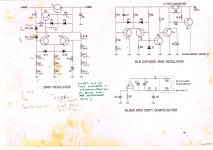
Use a latching relay, and a manual reset.In the notes the man stated that he battled with the overload that reset itself after a short while - he wanted it to stay latched when it tripped.
There is an error in the amplifier schematic on the secondary, the tap with feedback connection is shown as grounded, the other tap should be unless the intention was to defeat the global feedback. This is no question a very complex amplifier.
The over current protection lacks an implicit latch function from what I can see.
The over current protection lacks an implicit latch function from what I can see.
Last edited:
I think the output connection is just missing a dot between R27, R28, and the lower, hot output lead.
The upper, grounded output lead is right.
He's using the convention of jumpers and no dots, instead of dots and no jumpers.
I'd rather use jumpers and dots both, so things cannot be ambiguous.
The upper, grounded output lead is right.
He's using the convention of jumpers and no dots, instead of dots and no jumpers.
I'd rather use jumpers and dots both, so things cannot be ambiguous.
Rayma, you are correct when I look at it again. He was following an obsolete drawing convention and it did not register until you mentioned it. I drew schematics that way when I was very young. 😀
That's the way the old genius drew it.I think the output connection is just missing a dot between R27, R28, and the lower, hot output lead.
The upper, grounded output lead is right.
He's using the convention of jumpers and no dots, instead of dots and no jumpers.
I'd rather use jumpers and dots both, so things cannot be ambiguous.
Rayma, you are correct when I look at it again. He was following an obsolete drawing convention and it did not register until you mentioned it. I drew schematics that way when I was very young. 😀
I did too, but soon changed when the schematics were illegible, even to me.
Just a few ideas of where to start:
1. Those output transformers need to be measured.
Turns Ratios
DCRs
Leakage Reactance
Plate and Cathode primary inductances
Total Weight (laminations + copper)
And properly driven and properly loaded:
Frequency Response
Square Wave Response
Phase versus frequency
2. Or, build the amplifier, with simpler circuits (no solid state circuits) check all the DC parameters, kill any oscillations, etc. and measure the performance, without negative feedback, and measure with negative feedback.
Hint: Start with individual self bias for all 4 of the parallel push pull 6L6GC tubes to make turn on easier, and no burnout of the output tubes at first power on.
Just my opinions
I agree , remove all the silicon , and lower HV to something more manageable.
I would install per tube grid bias .
Forget the aim of achieving 100wpc , go for a more realistic 60-70W in UL
I would install per tube grid bias .
Forget the aim of achieving 100wpc , go for a more realistic 60-70W in UL
- Home
- Amplifiers
- Tubes / Valves
- 6L6 Power Amplifier - A grandmasters unfinished dream