Was post #1. Rename PSoup2.asc.txt to PSoup2.asc
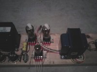
Anyways, I got some workin'progress pics of it,
Thats an old 6BX7 LTP I had originally planned...
Use this weekend to get fixed bias pots wired maybe?
Anyways, I got some workin'progress pics of it,
Thats an old 6BX7 LTP I had originally planned...
Use this weekend to get fixed bias pots wired maybe?
Attachments

Even if I know this an early version they sim with rather high distortion as is. Raising the Iq bettered this considerably. Did you get the same result?
Do I see a 10 pounder for power? If so I am using 2 of them to power my red board. Each has its own FWB and 470 uF cap. The output of each bridge is wired in series. This gives me 630 volts with no load and 600 volts at 100 WPC. It also gives me 300 volts for the low level stuff.
Yep, voltage doubler with 10lb in series with 30uF to block DC.
Got 650V without load, but expecting this to sag considerably.
Filaments are not even wired yet...
I'm waiting for the XRay machine to be idle, see if I can sneak
a few upskirts of 6BG6GA for curiousity. I see some websight
selling Phillips/ECG as special 35W plate, not 19W? Phillips/ECG
indeed I have, but not sure if 35W claims are true or sales BS.
Imagine two 33ohm in series, 10H in parallel across the sum.
Then from the mid of the 33ohms, a series pair of 470uF to
ground. 100K bleeders on each. Like a big T with the choke
across the top. And 1uF at the output. Trying a circuit that
might be immune to ringing? L and C are neither in series nor
in parallel, excepting the 1uF.
Last edited:
Even if I know this an early version they sim with rather high distortion as is. Raising the Iq bettered this considerably. Did you get the same result?
Definately 30mA (18W idle) is low. If the plates can take 35W, I will up this.
Wish I could dump more Iq into the AX7, and contemplating parallel both halves.
A stiffer AX7 plate current source might help, but I want to try out the freebie
bleeder across VBE first.
Last edited:
Phillips/ECG indeed I have, but not sure if 35W claims are true or sales BS.
True 6BG6's have a 19 watt plate. Sylvania and Phillips/ECG did a lot of creative glass stuffing at the end of the vacuum tube era to fulfill contractual obligations. The most famous case is the tubes marked 6B4GA (A DHT)that contain triode wired 6AV5GA guts (a sweep tube pentode).
They did stuff 7027A guts into 6BG6GA glass (with 6BG6 pinouts). It is not known if all Phillips ECG 6BG6GA's are made this way, but the tubes sold by SND sales are really 7027A's and will eat 35 watts with a smile. I stuck a pair in a Bandmaster (with adapters) about 2 years ago and they are still cranking.
Note: The Philips EGC 6CW5's contain some wimpy little pentode and they will self destruct in many 6CW5 amps including the Simple P-P.
http://www.diyaudio.com/forums/tubes-valves/130597-grid-screen-alignment-x-rays-13.html#post2448703
See Post#122
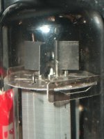
Does this look more like the 19W or 35W in your experience?
See Post#122
Does this look more like the 19W or 35W in your experience?
Does this look more like the 19W or 35W in your experience?
Don't know since I never saw X-rays of either. I dissected several 807's and old style 6BG6's a few years ago since they were broken. I only had the pair of SND tubes and I didn't buy then the Bandmaster owner brought them with the amp since he had no idea how to make them work.
Compare the plate structure to a 6L6GA, 807 or old style coke bottle 6BG6. It should be bigger with larger wings. This looks to be the case in the x-rays. The test is obviously to plug them in and crank them up. A "normal" 6BG6, 807 or 6L6GA will show obvious redness at 25 watts. The "super" 6BG6 does not at 30 watts.
I looked again at your X-rays. They don't tell me much. The clue is in the text. The date is July 1985 from the end of vacuum tube production. There is a FSN (federal stock number). The tubes were made for a government contract. This means that you likely have the good ones.
In response to suggestions that P-MOSFET might be better? I've searched high and
low for something that will drop in place of MJE350. No such luck. Closest candidate
so far seems to be Phillips NXP's BSP230, unfortunately a tiny surface mount part.
It'll handle the 300V, but not the power. You'd still need a gate Zenier and an NPN
(in Sziklai pair configuration) to take the heat. Perhaps MJE340?
The gate drop seems to make for about 2x stiffer current source than VBE, and of
course no base current leak flowing to the plate. Yet for all "improvements", its not
that dramatically different than plain MJE350. I don't think I would bother...
.SUBCKT BSP230 1 2 3
Cgs 2 3 41.3E-12
Cgd1 2 4 148.7E-12
Cgd2 1 4 5E-12
M1 1 2 3 3 MOST1
M2 4 2 1 3 MOST2
D1 1 3 Dbody
.MODEL MOST1 PMOS(LEVEL=3 KP=10.31e-6 W=23e-3 L=2e-6 Rs=20e-3 VTO=-2.4 Rd=13.06)
.MODEL MOST2 PMOS(VTO=3.1 KP=10.31e-6 W=23e-3 L=2e-6 Rs=20e-3)
.MODEL Dbody D(Is=1.493E-14 N=0.9364 Rs=2 CJO=9.5E-11 VJ=0.9919 M=0.5697
+ TT=865.6E-9 BV=300 IBV=10E-6)
.ENDS
And remember, even if you paste this .SUBCKT into your LTSpice drawing:
PMOS symbol defaults to .MODEL and won't find or utilize .SUBCKT !
You have hold [control], then right click on the PMOS
Change the Prefix attribute from MP to X
Now .SUBCKT works fine
Hey Ken,
Think we can expect a lot more inductance from the Edcor. They spec the 25W SE to over 40H.
How does this one sim?
14H in series with 14H on the same core = 56H
Twice for series coils, twice again for shared core. 14 x 4 = 56
I don't think proportionally adding more simulated inductance would change much?
Assuming I keep the reflected impedance at 5K plate to plate.
You think 100W 5K CXPP is more? Its way beyond my low end LCR meter for sure.
The 55H figure I saw somewhere can't remember was only for the mere 50W...
---------
The 4ohm tap is grounded. Cathodes sit on "0" and "16" per ARC ST-70-C3 style...
Last edited:
A PP should should maybe be more than 100H(25H a side) but will not change anything but lowend response so no need for adjusting the sim.
Last edited:
I've never heard anyone complain the low end of any Edcor CXPP?
Add to this direct coupled cathode feedback of the actual output.
Not something I have plans to collapse in a corner to worry about.
56H fine for sim, reality will likely be more. LTSpice sometimes loses
its mind if you throw a numerically large (more than 20 on any tap)
inductor at it anyway... Especially if coupling coefficient < 1.
Last edited:
I don't have any Edcor P-P OPT's except for the littlest ones and they don't work so well. I can see ane hear obvious saturation with a Simple P-P, but they are 10 watt OPT's and I am feeding them 18 watts.
I have tried cathode feedback using the guitar amp OPT's that I have a bunch of. It doesn't work. I think that the symmetry of the OPT's is off enough that the distortion actually goes up when the CFB is connected up, especially above 5KHz. You will have to try the Edcors with and without CFB to see how they react. I have a set of huge Plitron toroidal OPT's and CFB works well with them.
I have tried cathode feedback using the guitar amp OPT's that I have a bunch of. It doesn't work. I think that the symmetry of the OPT's is off enough that the distortion actually goes up when the CFB is connected up, especially above 5KHz. You will have to try the Edcors with and without CFB to see how they react. I have a set of huge Plitron toroidal OPT's and CFB works well with them.
At some point in the near future I'll check to confirm 0 - 4 - 16
Voltage symmetry and any differences of DCR. Right now I'm not
anywhere near the amp, and its not anywhere near my best test
equipment. I'd probably have to drag it to work with me Monday...
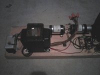
I have an identical OPT here somewhere, but lost track of it.
Other parts and stuff piled on top of everything. You'd never
know there is a working Williams Black Knight Pinball under all
that rubble somewhere. Yes...
Again we are talking the CXPP, and definately not the little one.
Voltage symmetry and any differences of DCR. Right now I'm not
anywhere near the amp, and its not anywhere near my best test
equipment. I'd probably have to drag it to work with me Monday...
I have an identical OPT here somewhere, but lost track of it.
Other parts and stuff piled on top of everything. You'd never
know there is a working Williams Black Knight Pinball under all
that rubble somewhere. Yes...
Again we are talking the CXPP, and definately not the little one.
Last edited:
I should have marked the drawing: 6BG6GA using 6L6 spice model.
Anyways, 300V sims much too low screen for single pair into 5K.
AB2 comes much too soon, blocking distortion almost unavoidable.
350V not making enough difference to justify a whole extra rail.
450V sims much better for a single pair, but 100V over max spec!
All the forward currents are then on G2, little or no leak on G1.
I suspect this might work, but suffer a very short screen life...
Upgrading to quad increases perceived plate load and everything
works much better now in AB1 at originally proposed 300V screen.
AB2 is available for transients, but continuous AB2 is still blocking.
Not so bad as one might think, cathode windings do swing +30V.
The threshold of AB2 blocking is over 100W, should I worry?
I could throw a heap more coulombs through that concertina and
use smaller grid leaks on the 6BG6GA G1's. But only increases the
length of AB2 transient tolerated, not fixing the actual problem.
I didn't want to increase my sand count, but Darlington simulates
much stiffer CCS for the 12AX7 plate. Better than any MOSFET or
MOSFET+BJT combo I had Spice models to test. MJE15035 seems
marginally superior specs to MJE350 all around, better in reality?
I wonder if its just the same old device in TO220 package...
Attachments
Well, seems blocking is my fault for overbuilding the concertina stage
and thinking I could then simply cap couple fake A2. Caps is an issue
no matter how much current any concertina can slew. The proper way
to cap couple might have been w. 22K grid stoppers and 22K grid leaks.
Do you know any examples where a lower value grid resistor (say 220)
to stop parasitics is used in series with a switch-out-able higher value
(say 22K) to prevent blocking. I mean like a switch you might throw to
change between listening room and MI duty.
There is no global loop here to aggrivate blocking. But still occours if
allowed to venture into A2 on a continuous basis. I'm pretty sure if I
plugged in my Bass, I'd have crossing distortions due to blocking in no
time...
Last edited:
If you want to draw significant grid current then your grid circuit must have a low DC resistance e.g. DC coupling or transformer. 22K grid leak is almost certainly too much resistance.
The idea that largish grid stoppers can stop blocking may be a myth. It all depends on the source impedance i.e. the output impedance of the previous stage. This is already in series with the coupling capacitor, and acts as a potential divider with the grid leak resistor. To stop blocking you either need to stop the capacitor from charging up too much during a brief overload (so large series resistance), or allow it to discharge quickly (so smallish grid leak). Large series plus smallish grid leak is a potential divider. It seems to me rather perverse to arrange a low impedance driver, then raise its effective impedance with a big grid stopper and attenuate its output with a smallish grid leak.
The idea that largish grid stoppers can stop blocking may be a myth. It all depends on the source impedance i.e. the output impedance of the previous stage. This is already in series with the coupling capacitor, and acts as a potential divider with the grid leak resistor. To stop blocking you either need to stop the capacitor from charging up too much during a brief overload (so large series resistance), or allow it to discharge quickly (so smallish grid leak). Large series plus smallish grid leak is a potential divider. It seems to me rather perverse to arrange a low impedance driver, then raise its effective impedance with a big grid stopper and attenuate its output with a smallish grid leak.
There is that Carver scheme of using a 6AL5 diode on the grid as a "base restorer". Draws equal current thru the coupling cap in the reverse direction to compensate. Connects to -2*Vbias.
- Status
- Not open for further replies.
- Home
- Amplifiers
- Tubes / Valves
- 6L6 amp with unique phase splitter - check my math