???
You can not derive triode model from pentode model ....
.
Why not? You always get triode model together when you paint a pentode model, don't you? Try it and I'll also try, action speaks louder.
Yes and no. The datasheet curves tend to be less reliable at low voltages where the tubes were seldom used. When I draw the same load line I see the -1V intersection as being closer to 2mA, meaning a 500R cathode resistor. Nevertheless, your measrements do look a bit further off than I would expect. Are you sure you have a 10k anode resistor and not something larger? It's also possible that your valve samples are rather old and worn out!
* Less reliable at low voltages
I tried three 6J1 tubes and got always similar results. How could the plot in the datasheet be produced for low voltages, if it can not reliably be measured?
* -1V / 500R
Your load line can be correct and mine a bit off. As written in the OP, I also tried a 470R resistor. With that I measured 0.75V and 1.6mA. With 500R the voltage should be a little higher and the current a little lower. Still too far from the datashee in my opinion.
* Correct resistors
I measured all resistors (metal film, 1%) several times (with two different multimeters) and they are 100% correct. So, yes. I am sure that the anode resistor is 10k. I also experimented with Ra=4.7k, but the results were similar off...
* Old worn out valves
This might be one explanation. But (at least) I thought that they are never used NOS tubes shipped together with the Little Bear P5-1. But this could be of cause a completely wrong assumption. If age alone really causes this degradation, then all tubes on the market should be more or less affected by that, but I could not find similar to mine problems using google...
Another reason you did not mention could be "natural" tolerances of the tubes. But, again, I tried three samples and got similar values for all of them. If tolerance is the cause, I would have expected to measure a notable difference between my three samples.
Maybe they are "fake" 6J1 tubes?
I will soon get some Mullard 5654 tubes from england. I will repeat my tests with them as soon as I receive them.
In the mean time, if anyone has some other explanations, I am happy to read them.
Thank you!
Klaus
Try it and I'll also try, action speaks louder.
I wish i can. I don't even know where to start. I simply can't comprehend how do we get triode model from pentode unless we want to get a very untrustworthy model. Sorry, i don't want to take this any further or i'll be accused of thread-jacking.
To OP:
I agree with Merlinb that at low Vak, things can sway a bit from the curve. He wrote a good article about tubes at low voltages. The manufacturer didn't intend for the tube to be operated around that area.. hence the recommended operating points. There just isn't enough potential to pull the electrons from the cathode reliably at that voltage. If everything's in order, including your heater voltage, i suggest to just trust your measurements and aim for the bias voltage you need.. and this basically answers your 2nd question. Aim for the bias voltage you need as too low Vgk will result in too early grid current on-set. Grid current can occur even before we reach Vgk=0.
AFAIR, 6J1P has 3'Ed grid connected to cathode, 6J2P has a separate leg.
Attachments
Last edited:
As Merlin said, if the datasheet already shows the triode characteristics, why do you need to bother with the pentode characterisitc.Well it's the way triode model is derived. It is possible for more than one triode model to be generated depending on the operating points. So you were given a triode connected pentode do you know what model you have being given?
Not if the model is reasonably well-built, but you are correct that the error will be greater if the operation conditions deviate greatly from the recommended values from the datasheets.As far I know to sim correctly especially with Pentode model, one must use a model based on very close Vg2 actually used.
That's a bit of stretch, why do we want so many different models?😕Since the modelling is not unique therefore it's possible for different triode connected pentode model hence the variation.
"That's a bit of stretch, why do we want so many different models"
I don't want so many different models, just too many model existed out there.
Attached is pentode model for 6j1, should be ok as I included the screen current and Vg2 data, but unfortunately the triode model is not accurate as compared with existing model. There is an incentive to make the model accurate since there are so many working pentode models, and to compare with existing model. There're people successfully converted to accurate triode model using this java painting software though. If you know what's up or down, please post here.
Attachments
Last edited:
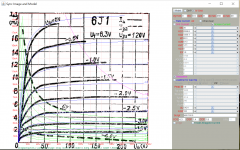
(Measurement: Rc: 1k, Uc:1.1V, Ic:0.95mA;....
Should not my measurements be much closer to the datasheet? (Measurement: Rc: 1k, Uc:1.1V, Ic:0.95mA;
Datasheet: Rc 556Ohm, Uc: 1V, Ic: 1.8mA;
Ra: 10k)
Klaus
1.1V/1k=1.1mA, why do measurement different from calculation?
Sorry, I mis-interpreted what you meant...I don't want so many different models, just too many model existed out there.
Yes, model paint tool is quite good, although I don't have much success with it to make the pentode models, the curves just don't line up too well for me...😱There're people successfully converted to accurate triode model using this java painting software though.
Heater voltage a bit low?
I didn't think about that. This could be another possibility. Tomorrow I will connect the heater to my adjustable power supply and repeat my tests with excatly 6.3V. I am curious how much the results will differ.
Best wishes
Klaus
I just experimented with the heater voltage.
10k anode resistor
470R cathode resistor
g1 with 100k to B-
g2 to anode
If I power the heater with 6.3V then I get a voltage drop of 0.76V across the cathode resistor. With 6V I get 0.73V.
So, the heater voltage is in my opinion negligible.
I have another stupid question:
When I connect the cathode and g1 directly to B-, then the load line should cross the 0V grid line in the graph (see post #2), shouldn't it? This means I should be able to measure a plate voltage of around 26V and approx 3.3mA through the anode resistor.
However, I actually measured a plate voltage of ~35V and 2.8mA through the anode resistor. This is not normal, isn't it?
Best wishes,
Klaus
I got today 3 pairs of matched tubes (RTC 5654, Mullard 5654, and russian 6J1P).
I just measured the RTC pair with exactly the same setup as in my previous post.
The RTC pair gives me 0.96V / 0.93V across the cathode resistor.
The Mullard pair gives me 0.93V / 0.93V.
The russian 6J1P pair gives me 0.78V / 0.80V.
In comparison my three chinese 6J1 give me 0.76V / 0.76V / 0.8V.
RTC & Mullard came closest to what I expected from looking at the datasheet.
The russion 6J1P & and chinese 6J1 deviate too much from the datasheet.
What did I learn: Never trust a datasheet, but always measure, measure, measure 🙂
For my next project with tubes I will use a pot to find out a good resistor value and not a calculated one from the datasheet ...
Best wishes,
Klaus
Last edited:
Thanks for the update, so perhaps we should treated the two types as similar - not as direct replacements for each other.
6J1 thread necromancy
Thanks, I needed that. Got one of those cheap preamp kits, but will be using it in an amplifier project, with a heavily modified circuit. Here's the nuts and bolts in a nutshell.
300V Ebb
Plate load=33KΩ
Self bias of around 7mA @ 2.5V gives a cathode resistor of 357Ω. Thinking maybe a 330Ω would be more practical... lol
Av≈20. No E follower needed!
Triode connected 6j1 you got from data sheet referred to screen Vg2 @120V, so now Vg2 only 60V, hence the variations. Anyway attached is the plot for 10k loadline, Vg2 120V, it's close to your finding. I think you stick to original first since it sounds good.
Thanks, I needed that. Got one of those cheap preamp kits, but will be using it in an amplifier project, with a heavily modified circuit. Here's the nuts and bolts in a nutshell.
300V Ebb
Plate load=33KΩ
Self bias of around 7mA @ 2.5V gives a cathode resistor of 357Ω. Thinking maybe a 330Ω would be more practical... lol
Av≈20. No E follower needed!
You can expect a well-made valve to be within maybe 30% of its datasheet. You cannot expect a valve to follow the datasheet of a different valve, even if many people say they are equivalents. Fortunately well-designed valve circuits are not too fussy about such details.kdre said:RTC & Mullard came closest to what I expected from looking at the datasheet.
The russion 6J1P & and chinese 6J1 deviate too much from the datasheet.
What did I learn: Never trust a datasheet, but always measure, measure, measure 🙂
I got today 3 pairs of matched tubes (RTC 5654, Mullard 5654, and russian 6J1P).
What did I learn: Never trust a datasheet, but always measure, measure, measure 🙂
Best wishes,
Klaus
Datasheet values for tubes are just average, tubes with exact datasheet parameters are pretty rare, for double tubes are very rare. We can find new tubes with +/- 30% or even +/-40%. Some russian datasheets says the range for parameters, western datasheets vary rare says this. For example Telefunken says they guarantee for E803CC max spread 15% for each section, this means we can find max 30% differences between the 2 triodes in a tube. And this is a special tube, high quality.
Tubes with 70% - 130% plate current are very good ones
Attached examples for 3 tubes 6J1P from a large batch tested by me.
Attachments
- Home
- Amplifiers
- Tubes / Valves
- 6J1 biasing inconsistencies with datasheet