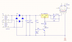
The heater uses 330mA at 6.3V. Which means the heater has a resistance of around 19 Ohm. The circuit I will use switches a resistor of 56 Ohm in parallel with the constant current source. So, for a number of seconds will be like 80mA across the resistor leaving around 250mA across the heater.
Then after the delay there is 327mA for the heater.
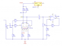
Here is my heater circuit:
Then after the delay there is 327mA for the heater.
Here is my heater circuit:
Attachments
Fancy! How much current is this circuit able to provide? Would it do 2X current for 6N6P? EDIT: of course. The 317 can do 1A even if it's fake. Here's my circuit.. SMPS, not battery. LOL
Attachments
Last edited:
The ECC86 system with TDA2050 Gainclone
How much gain would this tube circuit give? The TDA2050 power amplifier needs 0.39 Vpeak at the input.
I have changed the circuit to have 2.7k anode resistor. Across this resistor is like 12V. The triode is coupled in parallel = 1 tube per channel.
How much gain would this tube circuit give? The TDA2050 power amplifier needs 0.39 Vpeak at the input.
I have changed the circuit to have 2.7k anode resistor. Across this resistor is like 12V. The triode is coupled in parallel = 1 tube per channel.
Attachments
I got home the material today. Now is time to construct.
Biggest problem are the 2 tube sockets. The tubes are to sit on top of my box. The box is of massive aluminium. Think it is like 2.5mm thick. Now the sockets have a diameter of 21.5mm. That is the size of holes I must make. But how? This is my problem now.
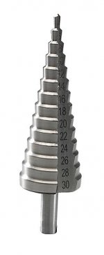
I will order something for my drillmachine - stegborr. Means step-drill. It drills step by step a bigger hole. Can make 30mm holes max.
Biggest problem are the 2 tube sockets. The tubes are to sit on top of my box. The box is of massive aluminium. Think it is like 2.5mm thick. Now the sockets have a diameter of 21.5mm. That is the size of holes I must make. But how? This is my problem now.
I will order something for my drillmachine - stegborr. Means step-drill. It drills step by step a bigger hole. Can make 30mm holes max.
I also use a step drill, and it's a vast improvement over a hole saw. 9 pin sockets usually require a 7/8" hole, 22mm is probably easier to find than 21.5mm and will work fine. Here in Canada I can't even find metric drill bits!
Last edited:
Metric stepped drills can be had very cheaply online. I just recently acquired a set of them. Not sure why, just wanted to fill out the toolbox.Here in Canada I can't even find metric drill bits!
Good to know. I'm waiting for this to go on sale: MAXIMUM M2 Steel Step Drill Set, 3-pc | Canadian Tire
But I use these: Mastercraft Titanium Nitride-Coated Step Drill, 2-pc | Canadian Tire They go on sale for $17 every couple of months.
But I use these: Mastercraft Titanium Nitride-Coated Step Drill, 2-pc | Canadian Tire They go on sale for $17 every couple of months.
Last edited:
Hello!
This kind is more flexible, for any diameter
reichelt.de
BOHRER BS3-30,5
(Can't put the correct link here)
This kind is more flexible, for any diameter
reichelt.de
BOHRER BS3-30,5
(Can't put the correct link here)
Last edited:
According to Philips datasheet ,curves B shows very linear transconductance variation on Va= 25v Ia 5ma Vg=0.7v . At this operating point the tube generates exclusively even order harmonics . It works from 3ma to 7 ma .
Yes. -0.7 is a good point. There was another guy in beginning of this thread that mentioned vgs -0.75V I will look at what you recommend. 25V 5mA
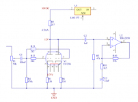
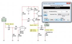
This is my latest thinking.. I use 0.70 Volt in the cathode. The anode voltage is 23 Volt. This gives 7 Volt across the anode resistance. This gives a ration 10:1.
Each tube delivers around 4mA and they are in parallel to lower output impedance.
This is my latest thinking.. I use 0.70 Volt in the cathode. The anode voltage is 23 Volt. This gives 7 Volt across the anode resistance. This gives a ration 10:1.
Each tube delivers around 4mA and they are in parallel to lower output impedance.
Attachments
I am thinking using slowstart is not necessary.
Not when I will use LM317 in Constant Current mode to supply the tube.
Also I have changed about using TRIODE in parallell.
I now design for using only one half tube per channel.
Not when I will use LM317 in Constant Current mode to supply the tube.
Also I have changed about using TRIODE in parallell.
I now design for using only one half tube per channel.
Headphone amp based on ECC86 low volt tube
Today I finally got a good spice model for ECC86.
The provider is @cogsncogs
So, I start this thread again with a new circuit.
The circuit has got rather low THD distortion.
Today I finally got a good spice model for ECC86.
Code:
* ==============================================================
* ecc86 LTSpice model
* Rydel model (5 parameters) mean fit error 0.0841046mA
* Traced by Wayne Clay on 03/31/2021 using Curve Captor v0.9.1
* and Engauge Digitizer from Philips datasheet.
* ==============================================================
.subckt ecc86  P G K
    Bp  P K  I=((0.06448068329m)+(0.02426328916m)*V(G,K))*uramp((11.97388325)*V(G,K)+V(P,K)+(5.140204023))**1.5 * V(P,K)/(V(P,K)+(0.5451602865))
    Cgp G P 2.0p ; 0.7p added (1.3p)
    Cgk G K 3.7p ; 0.7p added (3.0p)
    Cpk P K 2.0p ; 0.2p added (1.8p)
    Rpk P K 1.0G ; to avoid floating nodes
    d3  G K dx1
.model dx1 d(is=1n rs=2k cjo=1pf N=1.5 tt=1n)
.ends ecc86So, I start this thread again with a new circuit.
The circuit has got rather low THD distortion.
Last edited:

The current handling ability of that little 6GM8 is quite surprising.
Will you be breadboarding this design to give it a listen?
Will you be breadboarding this design to give it a listen?
This is the most interesting suggestion.None of the above, an SRPP stage (+B=60V) will have lower THD, mostly second harmonic.
But ECC86 can have max 30 Volt.
So, +60 Volt is probably too much.
Can I use +30 Volt across the SRPP stage?
The two halves of the tube are in series, so each one only sees 30V of the 60V total supply.
A mu follower is another option for low THD, and can be built as a hybrid with solid state devices acting as the CCS and the tube provides the gain. This would give a relatively low output impedance and would have low THD into a variety of loads, while SRPP tends to be optimized for a specific load impedance.
I built a headphone amp with 6GM8 about 20 years ago and remember it sounded nice, but don't recall any circuit details. Those valves used to be quite affordable, but prices rose dramatically after the tube saw use in some commercial offerings.
- Home
- Amplifiers
- Tubes / Valves
- 6GM8/ECC86 Tube preamp for 30VDC supply