Here is the heater circuit I will use.
Very good, you are using DC on heaters, "tube guys" very often do not do that.
I bet you will be amazed by the sound of your preamp.
I grew up soldering transistors, now I hate their sound, I never tried lateral MOSFETs anyway.
If using DC on filaments, constant current is a great way to go. I usually use AC, but hard to beat a CCS.
I always use DC on heaters, but never with a CCS because of the risk of thermal runaway on heaters designed for constant voltage, it can be done if experimentally determine the steady state current. On the other hand, with just a couple of valves, it should be easier.
AC on heaters is prone to intermodulation, even in indirect heated valves, via the AC magnetic field and cathode-heater capacitance.
Another advantage to use DC is that you can implement a soft-start circuit which prolonge valve life.
AC on heaters is prone to intermodulation, even in indirect heated valves, via the AC magnetic field and cathode-heater capacitance.
Another advantage to use DC is that you can implement a soft-start circuit which prolonge valve life.
Are you sure? The datasheet say: Pin 9 is to 'Internal Sheild'. But that is not to heater, so maybe you are right.According to Philips data of ECC86, pin 9 is not connected to the heater at all.
So one heater pin should also be grounded.
By the way, my tubes are from Telefunken
Last edited:
This consistent rant tubes are more linear the SS is pure bunk. I can get 0.01% distortion at 3v p-p from a npn single transistor amp gain of 10 B+ of 25v. A 6922 produces way more distortion but tube distortion is very musical and sounds fantastic if at the proper 1- 3 % second harmonic. To much tube sounds mushy and lifeless. Tubes do not exibit any kind of vbe 0.7v turn on /off knuckle or latchup like bjt transistors. They are most closely like a Jfet transistor.
The open-loop voltage to current transfer curve of a triode is less curved than that of a bipolar transistor, in that sense they are more linear. At constant Vak or Vce:
Triode: Ia ~= (Vgk + constant)^(3/2) with the constant being several volts
Bipolar: Ic ~= Is exp(Vbe/(kT/q)) with kT/q ~= 26 mV
That doesn't mean that each valve circuit is necessarily more linear than each transistor circuit, of course.
This looks like fun Lineup. Another project for me, I’ve been wanting to try tubes also. Subscribed, thank you🙂
Glad to hear 🙂This looks like fun Lineup. Another project for me, I’ve been wanting to try tubes also. Subscribed, thank you🙂
The first thing you should do, is to buy these low voltage tubes.
Search for 6GM8 or ECC86. Myself could find 5 tubes in Sweden. Costed me 12€ per piece.
This is the circuit I have now.
The working current is 5mA - 2.5mA per each of the two parallel triode halves. The voltage gain is around Vgain = 4.
The circuit input voltage will be like 0.5 Vrms, like 0.707 Vpeak. for driving my Chip Power Amplifier at full output.
The output from the tubes will be max +/- 1.15 Vpeak. The voltage at cathodes will be like +/- 0.28 Vpeak.
Attachments
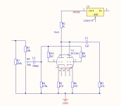
The trafo will be 30VA 2x24VAC I will parallel 2x24 to one 24VAC output. After rectifier the power supply will be like 33.5-36 VDC
The LM317T has a voltage drop of 2.5-3 Volt So I count on getting 30.0 VDC at the LM317T output.
Will be two LM317T .. one for each channel regulated supply.
The LM317T has a voltage drop of 2.5-3 Volt So I count on getting 30.0 VDC at the LM317T output.
Will be two LM317T .. one for each channel regulated supply.
Will be two LM317T .. one for each channel regulated supply.
Why two ?

I like to build real dual mono. There is one trafo and one rectifier bridge. But two LM317T - one for each channel. The two LM317T will be adjustable via potentiometer for exact 30.0 V output.
I have a question. In the tube sockets I bought, there is a connection in the middle. But there is no tube pin corresponding to that connection. Why is there such a connection in the middle?
I have a question. In the tube sockets I bought, there is a connection in the middle. But there is no tube pin corresponding to that connection. Why is there such a connection in the middle?
No. There's nothing like that.I always use DC on heaters, but never with a CCS because of the risk of thermal runaway on heaters designed for constant voltage...
I have a question. In the tube sockets I bought, there is a connection in the middle. But there is no tube pin corresponding to that connection. Why is there such a connection in the middle?
This is the connection to a tubular shield in between the pin contacts.
Best regards!
I have a question. In the tube sockets I bought, there is a connection in the middle. But there is no tube pin corresponding to that connection. Why is there such a connection in the middle?
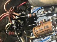
I could be wrong, but I think this could be used as a place to connect multiple connections, like ground, when doing point to point. I’ve got an old amp with something like this. Hard to see but the line in and a resistor from one of the puns are both connected. Coincidentally the tube in this photo is 6gw8, not 6gm8. Close 🙂
Attachments
Last edited:
Thanks.
So it seems I should connect pin4 or pin5 to ground. The heater. And also pin9 - the internal shield to ground. And also the mystery connection terminal in middle to ground.
So it seems I should connect pin4 or pin5 to ground. The heater. And also pin9 - the internal shield to ground. And also the mystery connection terminal in middle to ground.
Last edited:
No. There's nothing like that.
For constant voltage
V = I R = constant
Tungsten, often used in heaters, has a positive temperature coefficient, i.e. its resistance increases with temperature. Clearly an increase on temperature yields an increase on resistance, which in turn yields a decrease on current, which in turn yields a decrease on heat, which in turn yields a decrease on temperature, the heater is self protected.
For constant current
I = V / R = constant
Clearly an increase on temperature yields an increase on resistance, which in turn yields an increase of voltage, which in turn yields an increase on temperature which in turn yields an increase on resistance, which in turn yields an increase on voltage (voltage hogging)
In extreme cases this yields a thermal runaway, Morgan Jones says that he has had a total of two heater failures in 30 years, and that is enough to me.
Last edited:
No. In their related datasheets for series heated tubes any tube manufacturer specifies a specific current that has to be maintained within close tolerances and the voltage that can be measured across the heater terminals after the warm-up period. A higher voltage would only occur if current is exceeded, too.
I'm not sure what MJ exactly meant in his statement, but it correlates well with my experiences that heater failures are to be observed rather seldomly, being it in parallel or in series heated tubes.
Best regards!
I'm not sure what MJ exactly meant in his statement, but it correlates well with my experiences that heater failures are to be observed rather seldomly, being it in parallel or in series heated tubes.
Best regards!
- Home
- Amplifiers
- Tubes / Valves
- 6GM8/ECC86 Tube preamp for 30VDC supply