^^^^
Vkk= -300Vdc
Ipq= 2.78mA
C7-8: 0u1 / 300V (These being your typical film type capacitors from Mouser)
Vkk= -300Vdc
Ipq= 2.78mA
C7-8: 0u1 / 300V (These being your typical film type capacitors from Mouser)
-300V.. If I switch the 6SL7/12AX7 LTP from a negative voltage tail to a CCS, I can simply double the old -150V supply, so that works. However, why is the current any less than 6mA if each CF draws 3? Is some current flowing from the ground to the left through the 250K resistor and 100K pot?
In any case, it's got to be super simple to get a CCS that spits out 2 to 2.5mA... I'll have a look online.
Thanks a ton, this thing will be cool once it's done 🙂
In any case, it's got to be super simple to get a CCS that spits out 2 to 2.5mA... I'll have a look online.
Thanks a ton, this thing will be cool once it's done 🙂
All right, here's what I've got so far. How does it look?
An externally hosted image should be here but it was not working when we last tested it.
sorenj07 said:All right, here's what I've got so far. How does it look?
There are a couple of problems there. No way is that LM334 thingy going to operate off less than two volts. You're gonna need a negative supply for that.
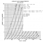
You're also gonna have to adjust the resistors in the bias networks. You stated earlier that you want to vary the 6F6 bias from -10Vdc to -30Vdc. This will require 6SN7 currents of:
(300 - 10) / 100E3= 2.9mA
(300 - 30) / 100E3= 2.7mA
From the loadline (attached) that means a Vgk= -5Vdc to -8Vdc, or a total grid voltage of: -15Vdc to -38Vdc. If you give it some leeway, -10Vdc -- -40Vdc, then replace the 2M5 resistor with 860K, and the 250K resistor with a 33K resistor. Keep the 100K adjust pot and its guard resistor, and the decoupling capacitors the same.
Attachments
All right. It makes sense that the loads would be different for this bias range. A -300V supply seemed daunting at first, but a small isolation transformer with a doubler should be OK. and if the LM334 doesn't like such a low voltage, I might as well just use the -300V supply to feed a nice long tail resistor for the 6SL7's. Maybe 280V to allow for some current draw as well as a decoupling RC filter.
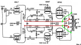
New schematic. Hopefully the details have been ironed out.
An externally hosted image should be here but it was not working when we last tested it.
^^^^
Yep, that looks pretty good. I would try the LTP without that 1K resistor on the grid of the bottom 6SL7 section first to see if it's stable without it. You could keep the stopper on the input half since it will contribute to RF rejection, even if it's stable without it.
Yep, that looks pretty good. I would try the LTP without that 1K resistor on the grid of the bottom 6SL7 section first to see if it's stable without it. You could keep the stopper on the input half since it will contribute to RF rejection, even if it's stable without it.
^^^^
That local feedback topology is useful for getting UL action when you can't run the screens of the finals at the same voltage as the plates. That doesn't appear to be the case here with 6F6s. If you went ahead and did that anyway, then you'd need a screen voltage regulator.
Doesn't look like this is the place for that.
Miles Prower said:^^^^
Yep, that looks pretty good. I would try the LTP without that 1K resistor on the grid of the bottom 6SL7 section first to see if it's stable without it. You could keep the stopper on the input half since it will contribute to RF rejection, even if it's stable without it.
Cool, I'll grab the last few parts as I am able to and will build pronto! I have everything except the isolation transformer and a few resistors and caps.
Miles Prower said:^^^^
That local feedback topology is useful for getting UL action when you can't run the screens of the finals at the same voltage as the plates. That doesn't appear to be the case here with 6F6s. If you went ahead and did that anyway, then you'd need a screen voltage regulator.
Doesn't look like this is the place for that.
Hi Miles, I think you might have misread Boris' schematic... he is just suggesting to connect the differential driver's plate load resistors to the ultralinear taps to add a bit of symmetric local feedback. Bandersnatch e-linear feedback. The red and green lines threw me off -- they don't actually connect, and just suggest that they could go to the plates or screen taps depending on how much feedback is desired. The screens would still be connected to the UL taps on the OPT normally, so no regulation needed.
Hey, that makes a lot of sense. I'll save the picture, and sure, if I'm feeling adventurous, I'll wire it up like thatjon_010101 said:
he is just suggesting to connect the differential driver's plate load resistors to the ultralinear taps to add a bit of symmetric local feedback. Bandersnatch e-linear feedback. The red and green lines threw me off -- they don't actually connect, and just suggest that they could go to the plates or screen taps depending on how much feedback is desired. The screens would still be connected to the UL taps on the OPT normally, so no regulation needed.

If ya don't have a scope to check out what's happening when trying this stuff out, I would just stick to feedback from UL taps instead of plate taps. Sometimes it may limit power output or rob too much gain, making the amp hard to drive without a preamp.
Well I just so happen to have a couple. I'm not very good at working them and am not even sure if they are functional, but I figure I'll start hacking away at some point.Boris_The_Blade said:If ya don't have a scope
Got most of the major chassis work done. I'm just missing an IEC socket. One I got from Mouser was female instead of male 
I'm in the process of figuring out how I'm going to fit ALL of the above schematic into this little 12x8x2" box, without it being complete mayhem. At least I have plenty of terminal strips.
An externally hosted image should be here but it was not working when we last tested it.
I'm in the process of figuring out how I'm going to fit ALL of the above schematic into this little 12x8x2" box, without it being complete mayhem. At least I have plenty of terminal strips.
Email me for an IEC socket... I have a few dozen used ones, filtered and plain, maybe even a fused one...
- Status
- Not open for further replies.
- Home
- Amplifiers
- Tubes / Valves
- 6F6G Amplifier