Hi Ed,
Your feedback curves are better, but they still don't make any sense. The output impedance drops with increasing feedback and flattens the response curve out. Your plots show just the opposite.
From my own experimenting it seemed that in one case, feedback improved everything until I reached 12 dB and higher. I settled on 9 dB worth of feedback for that specific amplifier. It seemed to be the best trade-off between improved sound and the sound being "squashed". I don't know if that makes any sense to you, but that was my subjective findings. Your feedback actually seems to be positive.
The low frequency rise could be supply hum with the bin size set too high. Or it might be an indication of a tendency to motorboat. I don't know if this helps you at all. I hope so.
-Chris
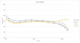
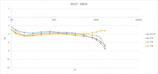
Hi Chris, I believe they do make sense. Let's assume lower fr bump is hum, I will work on fixing it by beefing up the capacitors in power supply. I found one typo in the numbers, insted of 394 I typed 349, so that is just one point, but the line showed the trend anyway. So here is the detail of previous responses. I do believe that they make sense. There is obviously biggest rollof without feedback, and by inserting negative feedback from highest resistor value to lowest, the rollof is smaller, and at 10k ohm, it even goes up. So perhaps around 20k ohm, it could be completely flat.
Completely other issue is the distorion, but as I said, I have no way to measure it, I can just look at sine wave on small hand held oscilloscope. Does anyone know simple free software I can download to see spectrum. It does not have to be top of the line, just simple pc based app.
Completely other issue is the distorion, but as I said, I have no way to measure it, I can just look at sine wave on small hand held oscilloscope. Does anyone know simple free software I can download to see spectrum. It does not have to be top of the line, just simple pc based app.
Attachments
Hi Ed,
I'm use to dealing in dB, so resistor values are throwing me.
If you are going to use a sound card, be extremely careful not to exceed 5 volts peak! Sound cards are not expecting amplifier outputs into their inputs and it is easy to kill a sound card. Rightmark might do what you need of it.
-Chris
I'm use to dealing in dB, so resistor values are throwing me.
If you are going to use a sound card, be extremely careful not to exceed 5 volts peak! Sound cards are not expecting amplifier outputs into their inputs and it is easy to kill a sound card. Rightmark might do what you need of it.
-Chris
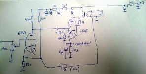
The 4 schematics you posted each have different components and component counts in the feedback loop. Which one is correct?
Dave G removed all of the feedback components except the 6.8k resistor and changed that to 10k when he replaced the transformers (https://www.tubesandmore.com/search/node/p-t31). He also added a 47 ohm resistor and .1uf capacitor in series as zobel network across the output.
In his initial test he posts oscilloscope images for a 1khz sine wave at the onset of clipping, a 2khz and 10khz square wave. The sine wave shows asymmetrical clipping. The 2khz and 10khz square waves do not even resemble square waves. The 2khz one shows strong ringing.
I would measure the voltages at grid and plate and current at cathode of both channels to determine operating point. Would you post oscilloscope images of the above referenced sine and square waves?
Hi all, yes, I will draw the schematics I am using, no problem. I can measure voltages as well.
Posting pics of oscilloscope is no problem, but it does not compare with spectrum analyzer. Thanks for the info Chris, I will look into it.
The sine waves looked very nice when I measured the fr response last time.
This amp always sounded great.
That square wave test is a great idea ArcticBrew, I do have a nice square wave generator somewhere, I may as well use it.
I think I should fix that little hum problem first.
Are you sure the 1k resistor is connecting the plate to screen? If it is then you are triode strapped.
Look at the El84 data sheet for triode operation. It specs a 270 ohm cathode resistor, 250 volts at anode, 36ma idle current, and a 3500 ohm impedance OT.
With a 4 ohm load the reflected impedance is going to be ~6500 ohms.
Now is the time to measure the impedance of the OT. It is easy. Connect an AC voltage to the primary and measure the voltage on the secondary.
If you want to use this amp in triode mode you need a different OT than the stock one...unless you have 2 ohm speakers. Maybe you don't have the stock transformer.
If you want to use the stock transformer then you should rewire it to operate in pentode mode.
I prefer the output tube in the triode mode, its more pleasing. I used it in pentode mode too as original schematics.
I can try 270 ohm if you think it could improve things.
I like to use original output transformers, i believe its part of the magic. Although i am expecting edcor se transformers soon, those will be for another project.
I can try 270 ohm if you think it could improve things.
I like to use original output transformers, i believe its part of the magic. Although i am expecting edcor se transformers soon, those will be for another project.
Triode mode is easy to implement and very good with this family of tubes.
If you go triode mode you don't need the feedback circuitry. You need feedback if you want to use pentode mode.
I use triode mode 6V6's for a high frequency amp feeding 98db efficient speakers in my lab (spelled garage). I like it.
The transformers that Dave G used were only $14. You could look for something similar in the proper impedance.
With the proper OTs it will be very easy to clean up this amp and get good sound.
I will most likely order those output transformers...you are right, they are cheap just to try it.
...and i became member to read audiokarma threads to educate myself. Thanks everyone, this is fun. I wish i had more time.
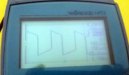
Btw what do you think about that square wave?
Btw what do you think about that square wave?
With decent transformers and the circuitry modified for a better operating point in triode mode it will look like a square up to 10k and beyond.
The magnavox transformers can provide very good results when the loading is correct. I would measure the impedance before making a purchase. If they are stock then you need to change them to run in triode mode.
What is the measured anode voltage and the voltage across the cathode resistor?
The magnavox transformers can provide very good results when the loading is correct. I would measure the impedance before making a purchase. If they are stock then you need to change them to run in triode mode.
What is the measured anode voltage and the voltage across the cathode resistor?
I would read thru the whole thread from Dave G before making the decision about triode vs pentode.
You mentioned headphone use. Is that the only use that you intend for this amp? Or do you plan to drive speakers with it?
If you don't have high efficiency speakers you may be better off with the 4+ watts you can get in pentode mode.
You mentioned headphone use. Is that the only use that you intend for this amp? Or do you plan to drive speakers with it?
If you don't have high efficiency speakers you may be better off with the 4+ watts you can get in pentode mode.
I will measure tomorrow...or when possible.
However...i just read in his post #87...that low fr hump is caused by too low cap to the grid of power tube. Interesting. Although i had blame it on slight hum, its most likely real.
However...i just read in his post #87...that low fr hump is caused by too low cap to the grid of power tube. Interesting. Although i had blame it on slight hum, its most likely real.
Final use depends of the amp depends...yes, it sounds great as headphone amp, but even just 2 watts for computer speakers is plenty. Desktop speakers are often small and inefficient. I just built 'nautalos' with 4" faitalpro, which is pretty efficient at 91 dB, for such a tiny speaker. Another potential desktop i am almost finished with is ac130f with small dayton dome, impressive for 5.5" midbass.
I got 15" coax with 98 dB, but that hardly can serve as desktop.
But headphone amp is most likely, as i have plenty of 15 watts chip amps, and those will be better for powering small bookshelf.
Frankly, i got so much stuff that i do not actually need it. I just built it for fun.
I got 15" coax with 98 dB, but that hardly can serve as desktop.
But headphone amp is most likely, as i have plenty of 15 watts chip amps, and those will be better for powering small bookshelf.
Frankly, i got so much stuff that i do not actually need it. I just built it for fun.
When you posted the schematic as built I thought you should decide what use you want for the amp and the circuit topology before we spent time addressing other issues that may not be relevant.
The .01uf cap and and 470k resistor provide a 34hz corner frequency at the input to the EL84 grid (simple RC high pass filter formula). That is probably a good choice with the stock transformers.
The choice of cathode bypass capacitor value will also affect the frequency response of the stage. I don't have that formula at hand but it is easy enough to find with a little searching on the Net.
You may find as I have that once you decide on the topology that provides what you want the basic components in the magnavox amp are more than adequate for your needs with the proper loads.
Decide what loads you want to drive and the loudness you want to obtain and then modify the circuitry to provide it.
Have you used any other faitalpro speakers?
I have been considering some of their offerings for a high efficiency mid-range.
I have been considering some of their offerings for a high efficiency mid-range.
- Status
- Not open for further replies.
- Home
- Amplifiers
- Tubes / Valves
- 6eu7/6bq5 feedback question