Please search my posts, you will find '2way with 6fe200' thread...right now its used in open baffle.
The .01uf cap and and 470k resistor provide a 34hz corner frequency at the input to the EL84 grid (simple RC high pass filter formula). That is probably a good choice with the stock transformers.
I perfectly understand that, I built numerous active crossovers, but it does not explain the hump...
That is good to hear. I have been looking at the 6fe and 8fe. What have you done with it?
http://www.diyaudio.com/forums/multi-way/282141-6fe200-st200.html
I am using it open baffle with selenium tweeter and 12" woofer, highly recommended mid
Thanks for the link. I am looking for something to use for a midrange with an Altec 416B and ESS AMT. OB for the mid and amt and probably some type of box for the Altec.
The Altec and the AMT are 98db efficient which is why I was looking at the FaitalPro line. I don't know if they will marry well together but, I am going to order the FaitalPros and get started.
I read your blogs. I like them. I know you understand all of this stuff.
Getting rid of the hum is important but, I would not spend time on anything else until the amp is functioning at a better operating point.
I have quite a few magnavox amps. They are not pretty but, for the money they perform quite well after some component upgrades and tweaking/tuning. My favorites are the biamped versions with the 10watt LF amps and the 3 watt HF amps
I have several GTA SE40 special editions and a pair of Chinese monobloc class A push pull 300B-845 amps. I like all of them a lot but, I don't like burning 500-1000 watts to get less than 1 watt to my speakers. So I tweak the magnavox amps and get a couple watts that I can live with.
Steve
The 4 schematics you posted each have different components and component counts in the feedback loop. Which one is correct?
Dave G removed all of the feedback components except the 6.8k resistor and changed that to 10k when he replaced the transformers (https://www.tubesandmore.com/search/node/p-t31). He also added a 47 ohm resistor and .1uf capacitor in series as zobel network across the output.
In his initial test he posts oscilloscope images for a 1khz sine wave at the onset of clipping, a 2khz and 10khz square wave. The sine wave shows asymmetrical clipping. The 2khz and 10khz square waves do not even resemble square waves. The 2khz one shows strong ringing.
I would measure the voltages at grid and plate and current at cathode of both channels to determine operating point. Would you post oscilloscope images of the above referenced sine and square waves?
Steve, i made it to his post #364 about the old vs new transformers, so i am not sure what i ordered. In any case i will measure and compare.
Hi everyone,
I made some progress, although small, but progress. I have added 2x100uF (400V) caps to the power supply, and hum is basically gone. I see small rumble ~2-3 mV on oscilloscope. Considering its a breadboard with no shielding, its pretty good for now.
I hear nothing with the ear at speaker.
Although I still do not have new transformers, I am fine for now with the originals.
I have briefly re-measured fr response, and see no hump in the low frequencies. I have rewired it back to original pentode, and while it seems that sound was better in triode mode, I do not have data for now to back it up.
I have uploaded the RightMark audio analyzer, and it seems perfect for what I need. Thanks Chris! Even this is free, it seems well done and offers quite a lot. There is no danger to overload input on soundcard, as the software has nice indicators before the measurement takes place, to adjust the levels. Because it measures both channels, I need to make some new cablings. I had it set to measure one channel, and listen to the other before. I tested quickly one channel, and it measured very flat, no hump, form about 30 Hz to 16kHz. Plus it shows spectrum, distortion, and so on.
What I am going to do next is to measure pentode and triode configuration, and see how it works, what data I have, and see how it sounds in both configurations. I may measure with or without zobel, to see the effect, I may measure with resistor and with speakers, and so on. I want to optimize the sound quality, not the wattage.
Its seems that 20k ohm resistor is good choice for feedback. I have not tested that parallel cap for phase yet...
When it comes to the use with headphones, I always use resistor load for transformer, so it sees proper load like speaker. See my blog what I mean...
Since the weather got much better, I have less time, but I do want to finish it.
Attachments

Last edited:
While I have still not received the output transformers, I made quite a few measurements with original ones. If you are interested, I can post some fr responses, distortion spectra and so on. Here are my observations so far.
First, I compared pentode and triode strapped modes.
Distortion at about 0.5 volt on the output, which is normal listening level, not full power, is about 0.159% for pentode operation, and about 0.255% for triode mode. Not surprising. Its hard to say which is better, both sound good, triode is sweeter.
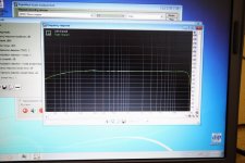
Both measure quite flat from 50Hz to 16kHz with single 20k ohm negative feedback resistor. This is best feedback. Amp slightly rolls of below 50 Hz, but still significant output at 30 Hz.
I tested capacitor in parallel to feedback resistor, that increased lower frequencies, but I did not like it, because it introduces hump. No need for that cap.
I tested with and without zobel, I see absolutely no difference whatsoever on parameters. Zobel is out.
One think I noticed, at first, I used my vaio laptop with external soundcard soundblaster extigy, old but good, which was giving me nice spectra, but now I have some computer glitch and RighMark Audio Analyzer software is not recognizing it.
I am using another laptop but without external soundcard, only the line in to the laptop. This has some distortion artifact. I know, because I can loop the signal in-out, without going into tube amp, and see how 1kHz sine wave spectrum looks like. It was much better with external card. I was curious to see spectral differences in triode vs pentode mode.
In general amp has noise floor down to -85 to -90 dB, however I still see 60Hz, 120Hz and so on artifacts. They are about -60 dB, but I do not like it, its affecting the results. I am going to work on DC for the heaters to brink it down. I know Magnavox never bothered too much, they even used normal untwisted wires. I want to achieve better than original performance.
That's all for now.
ed
First, I compared pentode and triode strapped modes.
Distortion at about 0.5 volt on the output, which is normal listening level, not full power, is about 0.159% for pentode operation, and about 0.255% for triode mode. Not surprising. Its hard to say which is better, both sound good, triode is sweeter.
Both measure quite flat from 50Hz to 16kHz with single 20k ohm negative feedback resistor. This is best feedback. Amp slightly rolls of below 50 Hz, but still significant output at 30 Hz.
I tested capacitor in parallel to feedback resistor, that increased lower frequencies, but I did not like it, because it introduces hump. No need for that cap.
I tested with and without zobel, I see absolutely no difference whatsoever on parameters. Zobel is out.
One think I noticed, at first, I used my vaio laptop with external soundcard soundblaster extigy, old but good, which was giving me nice spectra, but now I have some computer glitch and RighMark Audio Analyzer software is not recognizing it.
I am using another laptop but without external soundcard, only the line in to the laptop. This has some distortion artifact. I know, because I can loop the signal in-out, without going into tube amp, and see how 1kHz sine wave spectrum looks like. It was much better with external card. I was curious to see spectral differences in triode vs pentode mode.
In general amp has noise floor down to -85 to -90 dB, however I still see 60Hz, 120Hz and so on artifacts. They are about -60 dB, but I do not like it, its affecting the results. I am going to work on DC for the heaters to brink it down. I know Magnavox never bothered too much, they even used normal untwisted wires. I want to achieve better than original performance.
That's all for now.
ed
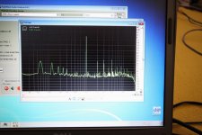
Well, the transformers arrived. But they are definitely faulty. They distort. Under the same conditions, about 6-7%. Spectrum is horrible, second harmonic is -20 dB or so below fundamental, others follow -5 dB like a square wave spectrum. Looks like clipping. Fr response is not linear, rolling of starting at 1 kHz, being -20 dB at 30 Hz.
Pretty pathetic performance.
Even worse, those transformers are internally buzzing. With resistors instead of speakers, I can clearly hear the buzz inside the transformers.
Complete fail.
Back to the originals.
Pretty pathetic performance.
Even worse, those transformers are internally buzzing. With resistors instead of speakers, I can clearly hear the buzz inside the transformers.
Complete fail.
Back to the originals.
Sorry to hear about the transformers. Dave is very rigorous in his analysis and this is a surprise.
You might join AK so you can tell your experience. Many of the members that have followed his thread are performing the modifications per his instruction. Perhaps there is a problem with the manufacturers quality and it would be good to know.
The only Magnavox amps that I have use 6V6 versions of that circuit so I cannot perform any tests that might aid in your diagnosis. I can measure and attest to the performance of the 6V6 version.
Steve
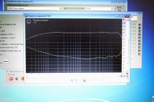
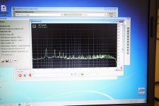
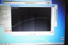
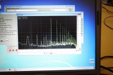
As you can see, its quite flat, slightly rolls of at low frequencies, but thats ok. I managed to get noise at 60Hz to below 60 dB, and general noise is -80 to -90 dB. Not bad. Now the 1k Hz spectrum is in reality even better, second harmonic down to -60 dB, third is however mostly contribution from poor builtin soundcard in the laptop. But thats ok for now.
This amp sounds great.
This amp sounds great.
- Status
- Not open for further replies.
- Home
- Amplifiers
- Tubes / Valves
- 6eu7/6bq5 feedback question