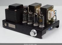
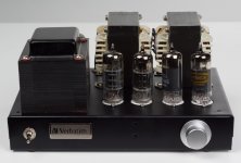
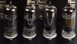
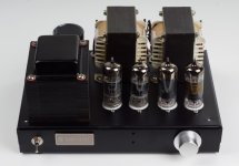
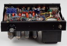
Output 2*12w Class-B
Posted this post, it is expected very few people will respond. Because it was too upset it. However, I do it well, and it is very good, in the output 2 × 6w when distortion is small, but has a good sound quality. Maximum output can reach 2 × 12W. Do not believe? Then you can try.
Shell is the CD drive of the shell, the entire tube amp with palm size.
Of course, a more powerful vacuum is entirely possible. I still want to use a smaller power vacuum tube for greater output.
As a result of the CLASS-B status, the whole tube amp static power consumption is very small.
Attachments
Last edited:
Do not believe? Then you can try.
I believe, because I made one. Try the 6HZ8. It has the same pinout but more power, with slightly different bias. It is physically bigger so it may not fit in your chassis.
I believe, because I made one. Try the 6HZ8. It has the same pinout but more power, with slightly different bias. It is physically bigger so it may not fit in your chassis.
Class-B too?
Dude, my bosom friend ah! ~
The thought that "unprecedented and no latecomers" it.
Last edited:
Class-B too?
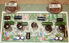
I designed a circuit board for use as a driver for some big sweep tube experiments. The board was designed to use any of the tubes that have the "9DX" pinout. I had 6GN8's in it for a while, and I have tried about 12 different tube types with 6BA8's in the board right now. I am using them for lower gain. I ran the board into an OPT and cranked it to see how much power it would put out. While not technically pure class B because there was a few mA of idle current, it was biased rather cold to boost the efficiency. I got about 15 WPC with the 6HZ8's. The board is now being operated in class A with mosfet followers for use as a driver in some high power class B type experiments.
There are a few of us here that have been experimenting with operation at the edge of class B to boost efficiency. Most of these experiments use TV sweep tubes and lots of clean power is the goal.
I have been working with class B type stuff for about 10 years. look at this thread for the latest experiments using this board:
http://www.diyaudio.com/forums/tubes-valves/237808-show-me-your-screen-drive-circuits.html
Schematic would be simple: one triode voltage amp, another triode phase splitter and then both pentodes as PP power stage. Cute little amp. Being European I'd use ECL82 which alas is not pin compatible.
Edit: hah- spoke too soon 😀
Edit: hah- spoke too soon 😀
I designed a circuit board for use as a driver for some big sweep tube experiments. The board was designed to use any of the tubes that have the "9DX" pinout. I had 6GN8's in it for a while, and I have tried about 12 different tube types with 6BA8's in the board right now. I am using them for lower gain. I ran the board into an OPT and cranked it to see how much power it would put out. While not technically pure class B because there was a few mA of idle current, it was biased rather cold to boost the efficiency. I got about 15 WPC with the 6HZ8's. The board is now being operated in class A with mosfet followers for use as a driver in some high power class B type experiments.
There are a few of us here that have been experimenting with operation at the edge of class B to boost efficiency. Most of these experiments use TV sweep tubes and lots of clean power is the goal.
I have been working with class B type stuff for about 10 years. look at this thread for the latest experiments using this board:
http://www.diyaudio.com/forums/tubes-valves/237808-show-me-your-screen-drive-circuits.html
Can you upload your schematic?
Last edited:
Schematic would be simple: one triode voltage amp, another triode phase splitter and then both pentodes as PP power stage. Cute little amp. Being European I'd use ECL82 which alas is not pin compatible.
Edit: hah- spoke too soon 😀
ecl82? good tube! why not ecl86?
Why not indeed! With almost double the allowable plate dissipation (9W) a pair of ECL86s will easily produce 14 watts of power with 300V supply voltage.ecl82? good tube! why not ecl86?
Yeah, but they have a slightly lower max plate dissipation (8 vs. 9W) than the E/PCL86 and they're intended for field oscillator/output in B&W TV. I did notice (from a Philips datasheet, thanx Frank!) that PCL85 and PCL805 are identical. Weird... In any case, from foraging along the streets in the seventies I have plenty of both types to swap myself silly 😀
PCL805 have 10.5W maksimal plate dissipation (see TELEFUNKEN data sheet), and in HOHNER ORGAPHON-24MH amplifier output power is more than 20W (Pentode connected, Ua=450V, Ug2=220V, fixed bias). My push-pull integrated amp. with PCL805s push-pull-UL connected outputs have ~14W output power from each chanell (Ub=2705V, automatic bias).Yeah, but they have a slightly lower max plate dissipation (8 vs. 9W) than the E/PCL86 and they're intended for field oscillator/output in B&W TV. I did notice (from a Philips datasheet, thanx Frank!) that PCL85 and PCL805 are identical. Weird... In any case, from foraging along the streets in the seventies I have plenty of both types to swap myself silly 😀
Can you upload your schematic?
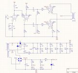
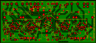
Here is the Eagle schematic for the driver board I used in the screen drive thread.
I test things bit by bit as it was being populated. The input triode LTP was populated first, and tested. The idle plate voltage can be adjusted via the CCS in the cathode. Next I populated the pentode pair except for the plate resistors. None of the mosfet circuitry was present. I wired a 10 K ohm OPT across the plates and connected it to a seperate power supply. The CCS in the tail forces class A operation where I got about 5 watts with the 6HZ8's. I put a 125 volt zener diode in parallel with the CCS to allow fixed bias operation. The idle current was set to a few mA via the CCS in the triode section. I cranked up the pentodes plate voltage until 15 W was seen. That was just to test the board.
I have now fully populated the board and have succesrully used it to drive a pair of 6CB5's to 180 watts in class B.
Attachments
Here is the Eagle schematic for the driver board I used in the screen drive thread.
I test things bit by bit as it was being populated. The input triode LTP was populated first, and tested. The idle plate voltage can be adjusted via the CCS in the cathode. Next I populated the pentode pair except for the plate resistors. None of the mosfet circuitry was present. I wired a 10 K ohm OPT across the plates and connected it to a seperate power supply. The CCS in the tail forces class A operation where I got about 5 watts with the 6HZ8's. I put a 125 volt zener diode in parallel with the CCS to allow fixed bias operation. The idle current was set to a few mA via the CCS in the triode section. I cranked up the pentodes plate voltage until 15 W was seen. That was just to test the board.
I have now fully populated the board and have succesrully used it to drive a pair of 6CB5's to 180 watts in class B.
good idea
Touché! You're right, but this is the "Design Maximum Rating", which prolly means a cherry red plate. Even so, 14 watts is perfectly attainable. Remains the question: does an audio pentode (PCL86) "sound better" than a field output pentode (PCL805)? I think it doesn't make a lot of difference, and in any case, I don't have an actual physical amplifier to test this. Back to my Dynaclone... 😀PCL805 have 10.5W maksimal plate dissipation (see TELEFUNKEN data sheet)
There is no CHERY RED PLATE at 10.5W plate dissipation of PCL805, and "sound better"(much) than PCL86 (also very good tube, but I use them only in small guitar amps)!Touché! You're right, but this is the "Design Maximum Rating", which prolly means a cherry red plate. Even so, 14 watts is perfectly attainable. Remains the question: does an audio pentode (PCL86) "sound better" than a field output pentode (PCL805)? I think it doesn't make a lot of difference, and in any case, I don't have an actual physical amplifier to test this. Back to my Dynaclone... 😀
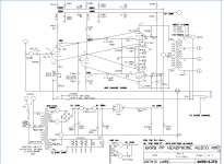
I did a PP PCB design using 6jt8, 6kr8 tubes for a small headphone amp. I was thinking it should be able to power 32ohm cans with little Merit A-2900 universal transformers rated at 4watts, it should be able to do 1/4watt output with GNFB . I was hoping that GNFB would help with the low and hi end where the little iron runs out of steam.... I started this idea a year ago but ended up making a 6LU8 version of this concept instead with 6CG3 diode that made a wonderful amp.
I will configure as 14K primaries 32 ohm outputs. I have a 6X4 tube as a slow warmup pass device in the B+ string...
Next will be to do a trasfer toner PCB, etched in a ziploc bag.....
I will configure as 14K primaries 32 ohm outputs. I have a 6X4 tube as a slow warmup pass device in the B+ string...
Next will be to do a trasfer toner PCB, etched in a ziploc bag.....
Attachments
I'll take that as a challenge, but will publish the results (if any) in a separate thread. Remember, this is the design maximum rating! 😱There is no CHERRY RED PLATE at 10.5W plate dissipation of PCL805
In any case, plate size of both tubes are similar.
- Status
- Not open for further replies.
- Home
- Amplifiers
- Tubes / Valves
- 6EB8\6GN8 P-P Output 2*12w Class-B