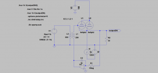
Simulation shows 0.196% THD at 180mVrms. this is predominately 2nd order.
Third Harmonic is down at 4.66e-5
4th is at 8.26e-7. (below -120dB)
I'm using Dmitry's triode mode model.
Third Harmonic is down at 4.66e-5
4th is at 8.26e-7. (below -120dB)
I'm using Dmitry's triode mode model.
Simulation shows 0.196% THD at 180mVrms. this is predominately 2nd order.
Third Harmonic is down at 4.66e-5
4th is at 8.26e-7. (below -120dB)
I'm using Dmitry's triode mode model.
Sounds promising Steven. Would you mind sending me your circuit so I don't start from scratch?
thanks
Ale
Here is the circuit and 6E5P_T model in a zip.
Thanks Steven. I thought you simulated what Lars was proposing. I can work from this one (which is same one as I had but with Dmitry's model).
Cheers,
Ale
Member
Joined 2009
Paid Member
Hi Bigun,
On the last edition of Morgan Jones' book he found that 6BX7 shows a big variance in distortion so these need to be manually chosen for audio use...
Cheers,
Ale
Thanks - that's a good tip to know about.
Think the whole idea of OTL is doubtful as the tubes are working in an unlinear area.
Add a 4:1 transformer after a single 6E5PT cathodefollower(hereticalstyle) and we are talking at least ten times lower distortion. Load is now in the ballpark of .5k. One have to watch the DCRs though, as these contribute to Zout. And is there a suitable transformer available??
You can dump the input transformer but need to keep the CCS to add necessary current.
Last edited:
Think the whole idea of OTL is doubtful as the tubes are working in an unlinear area.
Add a 4:1 transformer after a single 6E5PT cathodefollower(hereticalstyle) and we are talking at least ten times lower distortion. Load is now in the ballpark of .5k. One have to watch the DCRs though, as these contribute to Zout. And is there a suitable transformer available??
You can dump the input transformer but need to keep the CCS to add necessary current.
Hi Lars,
Will the classic Sy heretical stage be sufficient? Perhaps need some valves in parallel. Will simulate over the weekend.
Interesting proposal, however, need to check what OT could fit there...
Thanks
Ale
Attachments
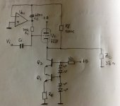
Here we go again. Well, 36mA of anode quiescent current per valve. Need three to get THD down to 0.10% at output voltage of 100mVrms. This is a nice operating point for the 6e5p, and FFT looks clean to me.
Is there a better choice of CCS transistors?
Only cap is input, which could be removed if an input transformer is used.
I think I should breadboard this one and listen to it?
Is there a better choice of CCS transistors?
Only cap is input, which could be removed if an input transformer is used.
I think I should breadboard this one and listen to it?
Attachments
Clearly that is one of the challenges here. Will need to test some and see if I can make a matched trio 🙄
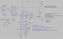
Running a pair at 100V and 60mA/tube gives us THD well below 0,1%. Ikmax=100mA.
Hi Lars,
I get 0.10% with a pair at 100V and 60mA per valve. Are these not being run very hot here?
thanks
Ale
Hey Ale,
The tube has Pamax 8,3W and Pg2max 2,3W. 100V*60mA=6W. So what is the problem?
An input transformer should also be used to get rid of the input cap.
No reason to go into details before you have found the best topology.
The tube has Pamax 8,3W and Pg2max 2,3W. 100V*60mA=6W. So what is the problem?
An input transformer should also be used to get rid of the input cap.
No reason to go into details before you have found the best topology.
Attachments
Last edited:
Also HT may better be 135-140V to allow valves to be biased at -1.3V to ensure there is no grid current distortion...
Hey Ale,
The tube has Pamax 8,3W and Pg2max 2,3W. 100V*60mA=6W. So what is the problem?
An input transformer should also be used to get rid of the input cap.
I can't remember where, but I think I read somewhere (perhaps at Romy the cat) that the 6e5p worked better at around 30-40mA....that is why I asked the question....
Has he built either a cathodefollower or a headphone amp?
It is your opinion that counts, not that from internetgurus.
It is your opinion that counts, not that from internetgurus.
You are right.🙂
Will build it with two and listen to it. On a breadboard I can easily add a third lady here. Will still need to match a pair though.
Will build it with two and listen to it. On a breadboard I can easily add a third lady here. Will still need to match a pair though.
Also HT may better be 135-140V to allow valves to be biased at -1.3V to ensure there is no grid current distortion...
Does 0,09% THD indicate any presence of what you guess😉?
Does 0,09% THD indicate any presence of what you guess😉?
Hmm. Wasn't sure if the valve model will reflect properly in the simulation the impact of the positive grid current here, can you please explain?
- Status
- Not open for further replies.
- Home
- Amplifiers
- Tubes / Valves
- 6e5p WCF headphone amp with no cap!