I wish I had an AVO!. After so much work managed to get my curve tracer working well. It's a challenge though to trace high gm valves, as the bias point tend to drift a bit so need to readjust just before taking the picture with the camera.
Will do some tests with the 6e5p when I get the time
thanks for the help
Will do some tests with the 6e5p when I get the time
thanks for the help
The risk of getting gridcurrent in a CF is extremely small wrt to the present signalvoltages.
About high Gm tubes you have to let them stabilize for at least 0,5-1 hour. I have an old AVOIII, it works great even with hi-Gm tubes like 6C45 etc.
About high Gm tubes you have to let them stabilize for at least 0,5-1 hour. I have an old AVOIII, it works great even with hi-Gm tubes like 6C45 etc.
Last edited:
Hi Lars,
Indeed, the valve stabilised after 20-30min. I managed to get a model very close to Dmitry's.
http://www.bartola.co.uk/valves/wp-content/uploads/2012/05/6e5p-triode-model.png
I may have recorded incorrectly the tracer settings as it seems like the grid start voltage was -2V and not 0V....
Here is the model
http://www.bartola.co.uk/valves/wp-content/uploads/2012/05/6e5p-spice-model.txt
Cheers,
Ale
I was looking at the datasheet of that valve and the lifetime is stated 500 hours ?!?!?!
In that case, maybe the Pa (max) is optimistic. Just a thought.
In that case, maybe the Pa (max) is optimistic. Just a thought.
I was looking at the datasheet of that valve and the lifetime is stated 500 hours ?!?!?!
In that case, maybe the Pa (max) is optimistic. Just a thought.
Indeed. However can't comment on that as haven't used it yet.
Interesting to see that there is a close brother of this valve, the 6e6pe. Longer life one with similar characteristics. It's a bit price though, but may be worth looking at this one as well....
Another thing to remember is that if you are using cathode bias, grid current does not start when the input signal peak is equal to the bias voltage in magnitude.
This is because of the feedback from the cathode resistor. In simple terms, when the input voltage is 1.3V peak and the bias is 1.3V, you induce an additional voltage drop in the cathode resistor of (24mA/V*1.3V)*32) = 0.998V !
Of course this becomes a cat-chasing-its-tail situation since the increased voltage drop reduces the differential due to the input voltage.
The arithmetic in your second sentence is wrong, but your third sentence suggests that you know this.
I have a stash(20) of 6E5P and i also got Lars old AVO😀
I guess it it is a good tube,they are all pretty cloes match.
Iwe got at least three quarters of 25 pice.
I guess it it is a good tube,they are all pretty cloes match.
Iwe got at least three quarters of 25 pice.
Go for 2*E182CC(4*triodes) instead!
I have 6N6P which are close equivalent to the E182CC I believe? gm is around 15mA/V as well per triode...
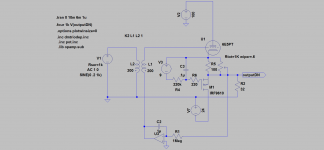
Interesting Lars. Can you please explain the topology, is it an anti-triode configuration?
thanks
Ale
thanks
Ale
Haven´t cared to name or define it😉. But anything with "mu" will do.
With P-channel depletion MOSFETs on the market it would have been even easier to accomplish.
With P-channel depletion MOSFETs on the market it would have been even easier to accomplish.
Haven´t cared to name or define it😉. But anything with "mu" will do.
With P-channel depletion MOSFETs on the market it would have been even easier to accomplish.
Well, it looks to me like a gyrator with a mu or anti-triode output (I think Michael Koster named it or referenced it as such), correct?
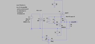
Same function. Gyrator this time🙂?
Indeed, but I thought that when the output was taken from a midpoint of the source resistor, that would provide the lowest Zout (Zout/2) compared to the gyrator equivalent?
Wouldn't that be the case when taking the output from the pot?
NO, no gyrator at all this time this time. Look at the battery as a signal short. If you take the output from the midpoint, Zout gets higher, not lower. When taken directly from the source Zout will be just a few ohms. When taken from the midpoint you will get a useless ballpark Zout of 30-40ohm. So Antitriode is no option here.
Ops, my fault. I didn't look at the circuit properly. So it's just a gyrator...
Will simulate this one then to study it a bit more, thanks!
Will simulate this one then to study it a bit more, thanks!
Noooo, the second one is NO gyrator, the cap can be omitted😉.
Question is wether the the battery would harm fidelity? No current through it so one could try Lithium cells. Thorsten L. used them in series with signal when adding grid bias. Think he bypassed with a small cap and a large resistor though.
Looking forward to your findings. Have never used and will never use headphones but I still find this subject amusing.
Last edited:
- Status
- Not open for further replies.
- Home
- Amplifiers
- Tubes / Valves
- 6e5p WCF headphone amp with no cap!