I want to make for a friend one 6DJ8/ECC88-SRPP Tube Preamplifier but I don't have on hand the 150uF, I have 100uF or 220uF, wich one can I use? have I to change the cathode resistor value?
If there is a way to upgrade the schematic your advice will welcome.
Wich value of pot for volume, I have 100K it's ok?
Wich value of pot for volume, I have 100K it's ok?
Last edited:
Either don't use an SRPP or optimize the loading- in a very nice article a few years ago, Merlin Blencowe showed that unlike common-cathode voltage amps, an SRPP will show a distortion null at some (relatively low) value of load. As well, the gain is extremely high for a line amp- he'll probably clip his power amp with the volume control barely advanced.
The schematic has a couple of glaring errors (the input impedance and the bias voltage). You could use a larger cap at the expense of overload recovery time. Or you could substitute a cheap red LED to get near-instantaneous overload recovery, some pretty light, and slightly reduced cost.
The schematic has a couple of glaring errors (the input impedance and the bias voltage). You could use a larger cap at the expense of overload recovery time. Or you could substitute a cheap red LED to get near-instantaneous overload recovery, some pretty light, and slightly reduced cost.
He has a clone Aleph X of 100W, what's the correct bias voltage?
I have on hand these LEDs:
1.8V 20mA Yellow water clear
1.9V 20mA Red
1.95V 20mA Yellow
2.0V 20mA Green
2.1V 25mA Greed diffused
Wich one do you recommend?
How can reduce the gain?
I have on hand these LEDs:
1.8V 20mA Yellow water clear
1.9V 20mA Red
1.95V 20mA Yellow
2.0V 20mA Green
2.1V 25mA Greed diffused
Wich one do you recommend?
How can reduce the gain?
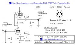
The 0.1 uF output cap seems a bit small for full range audio -- but it depends on the load. For a 10k load fc(-3dB) would be 160Hz with the 0.1 uF cap.
The 0.1 uF output cap seems a bit small for full range audio -- but it depends on the load. For a 10k load fc(-3dB) would be 160Hz with the 0.1 uF cap.
Thank you, do you know the input impedance of the Aleph X 100W?
Wich one do you recommend?
A cheap red LED will give you about 1.7V at the (roughly) 10mA this circuit runs, with very low noise and impedance.
The quoted LF point of 1.6Hz assumes no load (not even a scope probe!). I'm not sure where the input impedance of 240K comes from. The output impedance of 850ohms may be correct (I haven't bothered to do the calculation) but it will only apply above about 2kHz with a small output cap. Everything points to this design being done by someone who is new to audio and so ignorant of details.
I built several SRPPs (actually I am using it in my phono and line preamp). Here are my advices:
- You can go up with the B+ until 300V. A 350V filtering capacitor should be used in the PSU then. Good PSU filtering is essential, I use also local decoupling.
- You can eliminate the lower cathode capacitor. Gain will be about 16x, just suitable for line preamp. Linearity is also better. Some like the "softer" sound with cathode capacitor, though.
- To avoid oscillation, a small resistor (220R to 1k) should be soldered in series with the grids at the socket with short leads.
- Output impedance is about 1.2k.
- Input impedance is equal to the grid leak resistor.
- I use 1.5k cathode resistors, anode current is about 5 mA.
Omitting the lower cathode bypass will worsen PSRR. Whether this is significant or not depends on the quality of the PSU.
I built several SRPPs (actually I am using it in my phono and line preamp). Here are my advices:
- You can go up with the B+ until 300V. A 350V filtering capacitor should be used in the PSU then. Good PSU filtering is essential, I use also local decoupling.
- You can eliminate the lower cathode capacitor. Gain will be about 16x, just suitable for line preamp. Linearity is also better. Some like the "softer" sound with cathode capacitor, though.
- To avoid oscillation, a small resistor (220R to 1k) should be soldered in series with the grids at the socket with short leads.
- Output impedance is about 1.2k.
- Input impedance is equal to the grid leak resistor.
- I use 1.5k cathode resistors, anode current is about 5 mA.
-I can go till 300V for B+ but isn't too high?
-If I like cathode capacitor can I use 100uF or 220uF or other value?
-I will use Salas HV shunt regulator for B+, how much current draws the pre?
-OK 220R-1K in series with the grids
-Input impedance 1M?
Last edited:
Hello,
I am in agreement with SY the SRPP is very sensitive to load impedance. Where you take the output of the series arrangement shown will make the circuit no longer SRPP. Move the output to pin number 6. The gain will be ½ the mu of the triode at the operational point of B+/2 for each triode with a cathode resistor of 150R. A gain of ~15 is still way high in my view. Roll in a 12AU7 and see how you like that.
edit: remove the cathode bypass capacitor. This appliciation of series triodes has been around from the early 1940's or late 1930's.
DT
Last edited:
The schematic has a couple of glaring errors (the input impedance and the bias voltage).
You could use a larger cap at the expense of overload recovery time. Or you could substitute a cheap red LED to get near-instantaneous overload recovery, some pretty light, and slightly reduced cost.
Where is he substituting the LED? for a cathode resistor?
How to do per channel with two cascode 12AUT/ECC82 + half 6DJ8/ECC88 cathode follower? so five tubes (four 12AUT/ECC82 + one 6DJ8/ECC88) per a stereo preamplifier.
ECC82 cascode
Any schematic cathode follower ECC88?
ECC82 cascode
An externally hosted image should be here but it was not working when we last tested it.
Any schematic cathode follower ECC88?
Last edited:
This combo has too much GAIN!
Also the SRPP topology suffers from distortion. The 6DJ8/6922/7308 is a hard tube to find that the two sides are well matched. They are all over the place! Look at Morgan Jones BETA FOLLOWER in his book VALVE AMPLIFIERS. Pages 126-183-3rd edition. If this is a post volume control line amp then look at types 6J5GT and 12J5GT for the bottom tube. And seriously consider a 6EJ7, a pentode as the top tube. Jones gives some other examples he used for "test" circuits in in mu-follower as well to establish the distortion limits of this family of tubes. And dispense with that cathode resistor and cap and use a cheap red LED like SY suggested. Ray
Also the SRPP topology suffers from distortion. The 6DJ8/6922/7308 is a hard tube to find that the two sides are well matched. They are all over the place! Look at Morgan Jones BETA FOLLOWER in his book VALVE AMPLIFIERS. Pages 126-183-3rd edition. If this is a post volume control line amp then look at types 6J5GT and 12J5GT for the bottom tube. And seriously consider a 6EJ7, a pentode as the top tube. Jones gives some other examples he used for "test" circuits in in mu-follower as well to establish the distortion limits of this family of tubes. And dispense with that cathode resistor and cap and use a cheap red LED like SY suggested. Ray
What about this other 6922/ECC88 schematic?
Gain 22
Output impedance: 85 ohms, can drive headphones HD600 300 ohms?
Volume pot 250K

Gain 22
Output impedance: 85 ohms, can drive headphones HD600 300 ohms?
Volume pot 250K
Last edited:
What about this other 6922/ECC88 schematic?
Gain 22
Output impedance: 85 ohms, can drive headphones HD600 300 ohms?
Volume pot 250K
oh oh, Ive seen this schematic before,
and he's driving the 6922 too hard: taking it over its wattage rating.
But others have pointed out that there is nothing really to gain from that, except shortened tube life.
- Status
- Not open for further replies.
- Home
- Amplifiers
- Tubes / Valves
- 6DJ8/ECC88-SRPP Tube Preamplifier