Did you provide an individual bias adjustment potentiometer per tube, as yet recommended multiple times?
Best regards!
Best regards!
Not yet, but will do that later. If the one milliammeter works ok I might add a second one and do the individual bias pots at that time.
'Cause I'm convinced the faint (?) hum you're noticing results from bias imbalance between both tubes. A perfectly balanced PP amp should show no hum at all.
Best regards!
Best regards!

I know this been already suggested, so apologies for repeating it: I'd really recommend moving to self-bias. It will save you trouble, and the level of tube matching required is lower. You have plenty of B+ available. The ~11V cathode voltage is not going to cost you much power.
It's the same level, I'd say, 'cause self bias doesn't balance mismatched tubes. And self bias per se decreases efficiency dramatically.
In my experience mismatched tubes almost perfectly can be balanced by fixed adjustable bias, within limits, of course.
Best regards!
In my experience mismatched tubes almost perfectly can be balanced by fixed adjustable bias, within limits, of course.
Best regards!
I know this been already suggested, so apologies for repeating it: I'd really recommend moving to self-bias. It will save you trouble, and the level of tube matching required is lower. You have plenty of B+ available. The ~11V cathode voltage is not going to cost you much power.
The reason I moved from self bias is because it eliminates a cathode resistor and cathode bypass cap. Plus it increases the voltage to the tube slightly and I can set the desired cathode current by adjusting a pot.
'Cause I'm convinced the faint (?) hum you're noticing results from bias imbalance between both tubes. A perfectly balanced PP amp should show no hum at all.
Best regards!
Thanks for the explanation. Helps me understand why I have the hum.
Would be nice if someone made an analog meter specifically for tube amps that measured the voltage across a 1 ohm precision resistor and was powered by the tube heater winding and had the meter scale in mA. That way one meter could be used for both tubes and using a switch to select the tube won't be in the cathode circuit.
Last edited:
On my EICO 667 tube tester here's what the 7199 tubes read.
Installed 115
installed 108
spare 116
So I will install the tubes with 115 and 116 which should make the circuit better balanced.
With the choke shorted I get 1.8mVrms across the 4 ohm load.
I then get an output voltage of 7.25Vrms for a power of 13.14 watts for a no signal cathode current of 53.6mA which is as low as I can adjust it due to the maximum - bias voltage I have.
If I up the no signal cathode current to 70mA I get an output of 7.16Vrms for a power of 12.82 watts. I now get 2.16mVrms across the 4 ohm load with no input signal.
Last edited:
AC hum could be due to PP stage imbalance. Actually one of the ways to adjust balance is by minimal output hum.
Now I need to connect the speaker and see if I can actually hear the hum.
I can just feel the cone vibrate some.
What I don't understand is I only have 2.16mVrms across the speaker with no signal, yet I can feel the cone vibrate and hear it if I am closer to the speaker. Why is that so?
With the choke in place I do not feel the cone vibrate at all.
The speaker is the driver from a Grundig Hi-Fi-Raumklang-Box IV
https://www.radiomuseum.org/r/grundig_hi_fi_raumklang_box_iv_4.html
The speaker is rated at 6 watts so any power above that could eventually damage it.
In my experience mismatched tubes almost perfectly can be balanced by fixed adjustable bias, within limits, of course.
You can hear the improvement in bass response when the DC currents are well balanced. Give it a try.
You can hear the improvement in bass response when the DC currents are well balanced. Give it a try.
I did notice that improvement with a Magnavox AMP-142 I converted to fixed bias with two bias pots and two 100mA meters and here I thought the improvement came solely from eliminating the cathode bypass cap.
Haven't tried separate pots in a self bias amp, but it should work just as well there.
Just use large enough bypass capacitors.
Just use large enough bypass capacitors.
Instead of spinning your wheels endlessly wondering, why not try Google?Would be nice if someone made an analog meter
The first try got me this, no pain, suffering or agony. Help yourself rather than depending on others.😀
Attachments
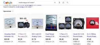
I'm not talking about those meters that require being inserted in the circuit to measure current.
I'm talking about a meter that can measure the voltage drop across a 1 ohm resistor and operate an analog meter with a scale of 0-100mA so that I can use one meter to measure the cathode current of each individual output tube. I'd use a SPDT center off switch to select which tube is connected. That way I do not need two meters and I don't have to worry about a switch in the cathode circuit failing causing a tube to have its cathode not grounded.
I'm talking about a meter that can measure the voltage drop across a 1 ohm resistor and operate an analog meter with a scale of 0-100mA so that I can use one meter to measure the cathode current of each individual output tube. I'd use a SPDT center off switch to select which tube is connected. That way I do not need two meters and I don't have to worry about a switch in the cathode circuit failing causing a tube to have its cathode not grounded.
Many of the analog meters in that list have a drop of less than One Volt.I'm talking about a meter that can measure the voltage drop across a 1 ohm resistor
Add a small value resister to get the One Volt drop if that is a priority..
Switch should have make-before-break contacts.
The Great Leveler is separate cathode bias resisters for those that would prefer.
Separate resisters reduce the difference in biasing voltage.
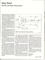
In 1960 there was no iNet or DIY to go too. To get results we all had to be
innovative. And think for ourselves. Subscriptions to magazines covering subjects
such as Radio & Electronics helped a lot.
Here is a solution I came up for two PP 6L6GC UL amps I built from the ground up,
my design. They still work today. 👍
This was published by AudioXpress much later in 1962.
What kind of Comm receiver are you working with?
And will it still work after you graft the PP 6BQ5 amp too it?😀
Attachments
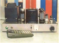
It's a receiver originally designed for headphones, but years ago I modded it with an audio output to drive the amp.
Been using the combination about 10 years.
Only recently decided it would work better if the receiver got its B+ and tube heater voltage from a separate power supply as there were issues with ground loops which is why I had to do the ground buss in the amp like I did.
Been using the combination about 10 years.
Only recently decided it would work better if the receiver got its B+ and tube heater voltage from a separate power supply as there were issues with ground loops which is why I had to do the ground buss in the amp like I did.
If the meter will be wired in parallel to a 1R current sensing resistor, you need a mV meter not a mA meter.
Resistance of the mV meter should be much larger than 1R, say 100R.
But first you need to determine the meter range by measuring the voltage drop across the 1R resistor at full output.
Resistance of the mV meter should be much larger than 1R, say 100R.
But first you need to determine the meter range by measuring the voltage drop across the 1R resistor at full output.
That's why I was hoping there would be an analog meter that is powered by a voltage available in the amp so that it can just measure voltage.
For now a 200mA meter between the single 1 ohm resistor and ground will work.
For now a 200mA meter between the single 1 ohm resistor and ground will work.
Analog meters are not normally powered.That's why I was hoping there would be an analog meter that is powered by a voltage available in the amp so that it can just measure voltage.
Do you mean a meter with a built-in DC amplifier?
I don't understand why you don't use individual current sense resistors with each tube.
Yes I meant that.
I was thinking how an analog volt ohmmeter which sometimes has the voltmeter powered is done, not realizing there might be confusion.
Would individual current sense resistors be better far as fixed bias is concerned such as using a 10 ohm resistor in each cathode?
I was thinking how an analog volt ohmmeter which sometimes has the voltmeter powered is done, not realizing there might be confusion.
Would individual current sense resistors be better far as fixed bias is concerned such as using a 10 ohm resistor in each cathode?
- Home
- Amplifiers
- Tubes / Valves
- 6BQ5 push pull amp conversion to fixed bias