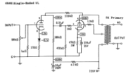
Just gonna say when I was building my 6BM8 amp, the LTspice crowd found all sorts of "This isn't going to work" things, and said I was using the wrong OT etc. It' works great, and more important sounds good. Testing with various impedance OT, the 5K one gave the best overall performance. What all these computer simulations don't do is show you what a design will sound like playing music.
Attachments


I tested the 8k, 5W transformers I got from Edcor, and they tested out deficient with respect to primary inductance - only 10 Henries. I think I'll be going with a set of Sony tape recorder output transformers intended for 6AQ5 duty I scored on Ebay. They test out fairly close to 5K:8 and have a much more respectable primary inductance of 21 Henries. Edcor is asking me to review the transformers I received from them. I think I'll just post the test results and let the fur fly...
The cheaper open core XSE Edcor OT IMHO do not work well for HiFi use, they are for guitar amp use only and even then not for a bass guitar. They are not the same OT as the GXSE type with end bells, just in a less expensive open core design. There is a reason they are cheaper! Their 10W and especially their 15W GXSE designs do work good for HiFi use.
And as I said, if you are using these tubes in a UL output tube design, 5K seems to be the sweet spot, especially run at the plate voltage I used, YMMV
BTW were you "test results" based on real world listening tests or testing of a built amplifier or a simulation/calculation?
And as I said, if you are using these tubes in a UL output tube design, 5K seems to be the sweet spot, especially run at the plate voltage I used, YMMV
BTW were you "test results" based on real world listening tests or testing of a built amplifier or a simulation/calculation?
My test results were based on actually testing the transformers in question - plunking the transformers down on the bench at my workplace and applying a 30V 300Hz sine waveform to the primary to measure the turns ratio, and from the exciting current, the primary inductance. I used a Fluke 87 meter to measure the output at the transformer secondary. Things did not look too good for the 8k 5W Edcors... I have specialty equipment at my work bench (variable frequency AC source, and a sophisticated AC analyzer (Yokogawa WT210)) used for characterizing SMPS. It's not a far stretch to use the same equipment to characterize output transformers. I do it for every output transformer that passes through my hands.
Last edited:
I don’t think good (even 80 Hz good) cheap and SE exist anymore. Even at 2 watts. I think it’s a corollary or a dual or whatever of Hoffman’s iron law. Iron, get it? I’ve long since given up on making anything inexpensive SE unless I get a donor transformer out of something. I have plenty of mini tubes laying around, I’ll just use two of the freakin things and get transformer that’ll work for twenty bucks. Plenty of other projects that are worth spending $100, 200 or 300 on the OPT.
I have a pair of Sony tape recorder SE output transformers that measure much better in terms of primary inductance. I had to pay more money for them than the Edcor 5W POS, but that's the breaks...
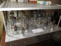
Good man.......there is nothing wrong using SMPS but there are knowledge caveats. I´ve been doing this for 60 yrs. The original 2x250W UL amp using KT90´s derated in pic to 2x115W using 6550C´s has a hard switched converter and there is no noise or hash, so long one understands the pecularities of RF. The superb characteristics of the power supply and using a fairly strung driver stage can sound the amp somewhat strident, but since one´s hearing response curtails with age, the definition is excellent.I have absolutely no problems with SMPS in a tube context. Properly shielded, they deliver the goods. As I've been designing SMPS for a living for over 40 years, I know whereof I speak.
Keep it up.
Bench Baron
Attachments
Since this a bitty little amplifier, it will be powered by a current fed push-pull DC-DC converter run from a 12V, 3.5A switching adapter. The tube filaments will be wired in series and run directly from the output of the adapter.
5670 with only 3mA is starved for current.
But for 3 mA, and more, I would try an IXYS IXCP10M90S
Just my opinion.
Never knock someone else's circuit down if it works for them.
If I need a 1ma current source, then I will try using an LND150. I can hardly wait (I need to design a circuit with a lower current tube).
Hmmm, 12AX7/ECC83; 5751, 6SL7?
Last edited:
6A3 -
The only thing that bugs me about the IXCP10M90S is that there are no capacitance specs listed, whereas I know that the LND150 is a very low capacitance part. If I'm going to recruit a part for current source load duty, I'll be wanting to know the capacitance associated with it.
The only thing that bugs me about the IXCP10M90S is that there are no capacitance specs listed, whereas I know that the LND150 is a very low capacitance part. If I'm going to recruit a part for current source load duty, I'll be wanting to know the capacitance associated with it.
Well the 1 milliohm load resistor on the input grid might be one of the things! Presume that's a misprint for megaohm (M)? It reminds me of a gotcha with Spice, in that it treats 'm' or 'M' as milli, you have to say 'meg' or 'Meg' for mega, can lead to very broken simulations if you fail to notice this...Just gonna say when I was building my 6BM8 amp, the LTspice crowd found all sorts of "This isn't going to work" things, and said I was using the wrong OT etc. It' works great, and more important sounds good.
Yeah - my PSpice installation has a problem with "M" in any form, so instead I feed it 1000k, 10000k, whatever..
I built one of Stephek designs. Sounds great. I use it at my desk. It drives tiny speakers whi h I plan on upgrading to a mini Franken.Just gonna say when I was building my 6BM8 amp, the LTspice crowd found all sorts of "This isn't going to work" things, and said I was using the wrong OT etc. It' works great, and more important sounds good. Testing with various impedance OT, the 5K one gave the best overall performance. What all these computer simulations don't do is show you what a design will sound like playing music.
Roger
wrenchone,
When I think I want to use a part, but am not sure how well it will work . . .
I build the amplifier, and measure the frequency response at the part in question.
Knowing the Miller Effect Capacitance of the tube that uses the CCS plate load, and knowing the next stages Miller Effect Capacitance . . .
That gives me a pretty good idea of whether the capacitance of the CCS in question is good, bad, or mediocre.
My experience with the IXYS CCS in my particular circuits . . . it works well for me.
I am a designer.
I am an analyst.
But I am always a measurement fiend. It is in my blood.
As you probably already know, I hate software.
Others can use simulation, Great!
But for me it is easier to build and test; than it is for me to fool around with software interface, and whether I am using it correctly.
Why do you think I have a number of chassis with power supplies already on them, just waiting for my next build to test a circuit idea, or a new part?
Now . . . where did I last put the soldering Irons to let them cool.
Last edited:
Well, I am going to try the 1.6 mA LND150 parts first and see how they fare - again, I'll be measuring, but with a gain-phase analyzer, with the twin goals of sorting out both the compensation and Zobel values. What works for you may not necessarily work for me, as the triode half of the Soviet 6BM8 is kinda anemic.
Try writing meg as in 1meg.Yeah - my PSpice installation has a problem with "M" in any form, so instead I feed it 1000k, 10000k, whatever..
I have not tried the latest version of LTspice I believe there have been quite a few changes.
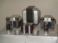
I found the same, the triode sections rather a disappointing performer when it comes to distortion. I spent much mettle on it, perhaps too much that in the end I changed the whole circuit to fixed bias operation resulting in a 9W+ 9W amp for 275V B+. It is capable of more. I abandoned the triode section and instead used an ECC88 as a cathodyne for a much better distortion performance that shows 0.05% at 9W for 20dB global nfb. It is an excellent sounder. The original o/p transformer used 20% UL taps whereas I got Sowter transformers now 40 years ago to provide 40% taps.as the triode half of the Soviet 6BM8 is kinda anemic.
The original 7W Mullard article which used the triode sections as a paraphase phasesplitter quotes less than 0.5% thd with 21dB global nfb. Naturally, one has to bear in mind the sales attractiveness that the original circuit was crammed into the smallest record player space that was common in the 1960´s designs.
I really ought to get alot of my earlier literature and designs stuck in ledgers from the late 1950 era tidied up and published.
The pic shows a pentode also in a first stage for MI as well as balanced input transformers.
Over the decades, by comparion to my other power behemoths that I designed, I can thoroughly recommend this easy small amp for HiFi with flexibility in either fixed or auto bias. It will astound many criticical listeners.
Bench Baron
Attachments
- Home
- Amplifiers
- Tubes / Valves
- 6BM8 Mini-Amp