a little bit of gas is ok. but it can go bad fast. I have some Chinese 2a3's that I got from a friend for FREE. Some were never used, but have a bit of gas.
Anyway they are for the most part fine. If you only have a bit of gas sometimes you can cook them and re-activate the getter.. but that's beyond this discussion.
You can search e bay for a single tube. right now I see lots for very reasonable starting price. Looking at the sold listings, I see quite a few that went for $10-$15.
Individually you can probably snatch up a bargain.
Last edited:

The glow in my tubes is way more purple than that. There isn't a hint of blue in my tubes.
OK, put in new tube, new hum pots.....still red plates....😕 Going back to my DC cilament supplies...should I ground the boards to amp ground?
The more I think about it, doesn't the DC filament supply need some kind of reference to ground? Right now, both supplies are grounded to the circuit board ground plane with no reference to the amplifier bus ground.
The filament supply should "float". It will be referenced to ground at the potential of the cathode bias. Something like 50 volts or so, whatever your bias is.
If you ground the filament supply, you could very well be shorting out your cathode bias resistor causing your "red plate" condition....
If you ground the filament supply, you could very well be shorting out your cathode bias resistor causing your "red plate" condition....
The filament supply is not currently grounded to any part of the amplifier ground.
That's good. What voltage do you measure from anode to filament? What voltage has the grid?
Hmm. So what DC voltage do you read at the top of your 6B4G's 1.2k ohm cathode resistors?
Maybe we need a picture of your build too..
Maybe we need a picture of your build too..
Well, I figured it out, well almost. I had the HV center tap connected to the buss ground instead of chassis ground. I fixed this and the left side works perfect, but tje right side still red plates but it takes about 3 times longer to do so. The right side also gets very very hot really fast. I checked myy wiring many times, not sure what is going on, but at least I have progress.
Good to hear you are getting closer. if you do click "go Advanced" you can add a picture to your post.
A picture of your build would help. Don't worry if you think it does not look pretty. Not everyone's builds are things of beauty.
A picture of your build would help. Don't worry if you think it does not look pretty. Not everyone's builds are things of beauty.
Good to hear you are getting closer. if you do click "go Advanced" you can add a picture to your post.
A picture of your build would help. Don't worry if you think it does not look pretty. Not everyone's builds are things of beauty.
I have decided to start over and I have already gutted it. I am going to rethink my layout this time. I noticed multiple mistakes with my grounding scheme. Hopefully This weekend I can rewire it.
I am wondering if I even need the regulated power supplies? I have a 6.3v filament transformer (with multiple windings) that I was thinking about using with a bridge rectifier and 10000uf cap
Last edited:
poor grounding scheme can lead to hum. but not to a red plate...
I tend to use "star" grounding but you can also ground to a bus. Both methods work very well.
I tend to use "star" grounding but you can also ground to a bus. Both methods work very well.
OK, so I just about got everything together for the new build, but I have a couple of questions:
6B4G cathode resistor value - Shouldn't this be around 750 ohm vices 1.2k as per the schematic?
62k 3W power supply resistor - Shouldn't this be closer to 27K to get the 280V and should both channels share this resistor?
One more thing - I purchased separate filament transformers for each 6b4g, but they have a center tap - would it be OK to ground the CT before the rectifier?
Last edited:
Don't ground the filament CT's unless you are using fixed bias. With cathode bias either the CT should be left unconnected if you have a separate cathode resistor/bypass cap or the cathode resistor/bypass cap should connect to the CT.
Don't ground the filament CT's unless you are using fixed bias. With cathode bias either the CT should be left unconnected if you have a separate cathode resistor/bypass cap or the cathode resistor/bypass cap should connect to the CT.
Copy that, thanks
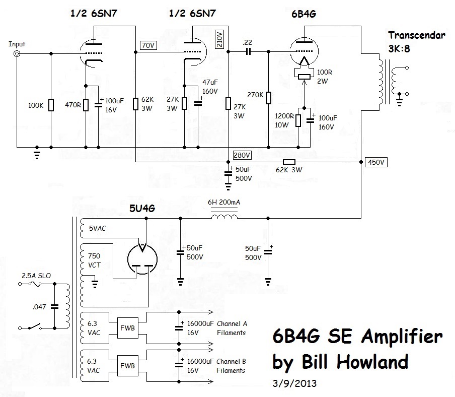
You mean 62K to drop 450V to 280V?
The division 170/62K results in 2,74mA.
My guess is that's just for two tubes, not for four.
So, four tubes would take 5,48mA and your power resistor should be 31K. Dissipated power is almost 1 watt so you better use a 5W or a 10W resistor.
- Status
- Not open for further replies.
- Home
- Amplifiers
- Tubes / Valves
- 6B4G New Amp Build Issue