What about the 67k power resister? Shouldnt it be 27k?
If you do the math for the current draw on the 6SN7 stages, you are correct. The 62k power resistor only drops about 3mA total for the voltages shown. You will need something around 28k to make the voltages work out as shown since both stages draw around 3mA each.
John
If you do the math for the current draw on the 6SN7 stages, you are correct. The 62k power resistor only drops about 3mA total for the voltages shown. You will need something around 28k to make the voltages work out as shown since both stages draw around 3mA each.
John
OK, So just of make sure, that would be 28K per channel correct? Also, isn't the cathode resistor too high @ 1.2K? Should it not be closer to 750R? The schematic is a little confusing as to what is shared between channels.
I was concentrating on the 6SN7 stages and I hadn't paid much attention to the 6B4G stage. Normally they are rated at 15W plate dissipation, 250V A-K and 60mA per the old data sheets. 450V for B+ is very high compared to the normally used voltages. 300B's run at that voltage. My guess is that the 1200 ohm cathode resistor is too low to keep plate current down to a reasonable level. I don't see how your tubes could last at all and I'm not surprised they red plated as you have an even higher voltage. A more appropriate B+ for a cathode biased SE 6B4G or 2A3 would around 300 volts with 50V of it across the cathode resistor. I think you've got the wrong power transformer and I don't see how the schematic above could work well for the output stage. You need to drop 200 volts across the cathode resistor to get the voltage across the 6B4G down to 250V. 200V @ 60mA would be a 3.3k resistor and would dissipate 12W, so you'd want a 20-25W rated resistor and it would make a lot of heat. If your B+ is a bit higher due to the 800VCT rating you need to measure it and calculate an appropriate cathode resistor to stay within the 15W rating for the tube.
Hope I got all this right. I think a new power transformer would the better choice.
John
Hope I got all this right. I think a new power transformer would the better choice.
John
I was concentrating on the 6SN7 stages and I hadn't paid much attention to the 6B4G stage. Normally they are rated at 15W plate dissipation, 250V A-K and 60mA per the old data sheets. 450V for B+ is very high compared to the normally used voltages. 300B's run at that voltage. My guess is that the 1200 ohm cathode resistor is too low to keep plate current down to a reasonable level. I don't see how your tubes could last at all and I'm not surprised they red plated as you have an even higher voltage. A more appropriate B+ for a cathode biased SE 6B4G or 2A3 would around 300 volts with 50V of it across the cathode resistor. I think you've got the wrong power transformer and I don't see how the schematic above could work well for the output stage. You need to drop 200 volts across the cathode resistor to get the voltage across the 6B4G down to 250V. 200V @ 60mA would be a 3.3k resistor and would dissipate 12W, so you'd want a 20-25W rated resistor and it would make a lot of heat. If your B+ is a bit higher due to the 800VCT rating you need to measure it and calculate an appropriate cathode resistor to stay within the 15W rating for the tube.
Hope I got all this right. I think a new power transformer would the better choice.
Yes, that is what I was thinking as well with regards to the power xformer. I am going to abandon this schematic all together and just use a 2A3 schematic to get this going. I really appreciate your help.
John
I think you can use the schematic for the audio circuit with just a few resistor changes once you swap out the power transformer. OTOH, there are many good SE 2A3 circuits on the web.
OK, so I got tne chassis all punched and will paint it this weekend.
I have decided on the Timebandit schematic I found online
The schematic calls for a 400-0-400 transformer fed into a LCRC filter
I found a very vice beefy transformer from an old oscilloscope with unloaded voltage of 460-0-460, which I think should equal approx 400-0-400 loaded. I may try and load it down with around 3000r 50w at the HV and see what the drop is just to make sure.
Attachments
Last edited:
Well, some things to consider:
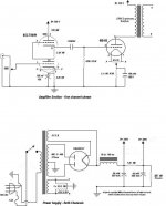
1- Power supply: With a choke input filter and 50uF on the plate supply, expect a fair amount of ripple which will pass through to the output as it's a single-ended topology. Also, note that the power supply is incomplete, you don't have independent filament supplies showing for the 6B4G outputs. You need one for each. What is showing is only used for the input/driver tubes.
2- Output stage: 470K is kind of high for the grid resistor. I suggest no more than 250K (249K is std. 1%). I've seen some 2A3 and 6B4G tubes develop some grid runaway with higher resistances. 2.7K is okay for a load, but having tested over 100 tubes (about 80- 2A3 and over 20- 6B4G), 3.5K is pretty much ideal. Better power with a bit higher voltage and lower distortion.
3- 6B4G DHT: Basically a 2A3 variant with a 6.3V filament and octal base. In most cases these are of the dual triode 2A3 construction with the filaments connected in series (dual triode 2A3 versions have the two filaments connected in parallel). As a result, you will need to provide a clean D.C. supply to each tube, otherwise the output noise will be quite high and the S/N ratio very poor making the amplifier close to useless.
4- Input/Driver stage: Not of fan of this topology myself but many seem to like it. You might have some limitations here as the output stage will require around 100 volts peak-to-peak drive. This could be at or near the limit of the driver which will limit overall performance.
Regards, KM
Well, some things to consider:
1- Power supply: With a choke input filter and 50uF on the plate supply, expect a fair amount of ripple which will pass through to the output as it's a single-ended topology. Also, note that the power supply is incomplete, you don't have independent filament supplies showing for the 6B4G outputs. You need one for each. What is showing is only used for the input/driver tubes
2- Output stage: 470K is kind of high for the grid resistor. I suggest no more than 250K (249K is std. 1%). I've seen some 2A3 and 6B4G tubes develop some grid runaway with higher resistances. 2.7K is okay for a load, but having tested over 100 tubes (about 80- 2A3 and over 20- 6B4G), 3.5K is pretty much ideal. Better power with a bit higher voltage and lower distortion.
3- 6B4G DHT: Basically a 2A3 variant with a 6.3V filament and octal base. In most cases these are of the dual triode 2A3 construction with the filaments connected in series (dual triode 2A3 versions have the two filaments connected in parallel). As a result, you will need to provide a clean D.C. supply to each tube, otherwise the output noise will be quite high and the S/N ratio very poor making the amplifier close to useless.
4- Input/Driver stage: Not of fan of this topology myself but many seem to like it. You might have some limitations here as the output stage will require around 100 volts peak-to-peak drive. This could be at or near the limit of the driver which will limit overall performance.
Regards, KM
Sorry, forgot to mention that I will be using two sperate transformers for the ouput filaments with each feeding into a bridge rectifier and 10000uf cap.
I will also be using James OPTs at 3.5k
What would you suggest for the power supply filtering?
I should also note that I will be using a foreplay II preamp with this amp, so I will not be putting a volume pot at the input.
Last edited:
I've done testing with some of the James OPTs... very good performers for the price. For the power supply, choke input filtering yields good regulation. I would add a second filter choke and filter cap. This would reduce the ripple significantly. You would also be able increase the second filter cap value to 100uF or possibly more.
For 6B4G filament supply, you might want to try a pair of large filter caps with a low value resistor between them, which you can calculate to give correct voltage. Using a center-tapped filament supply with a pair of diodes (Full-wave center-tapped) has less voltage drop than a FW bridge.
Depending on your plate voltage, you may want to try increase the cathode bias resistor. My 2A3 SET amps run higher voltage and an 866 ohm bias resistor. They also put out 4.5 watts before clipping. I run lower cathode current (~58ma) but higher plate voltage (~290) with plate dissipation closer to 17 watts.
Regards, KM
I've done testing with some of the James OPTs... very good performers for the price. For the power supply, choke input filtering yields good regulation. I would add a second filter choke and filter cap. This would reduce the ripple significantly. You would also be able increase the second filter cap value to 100uF or possibly more.
For 6B4G filament supply, you might want to try a pair of large filter caps with a low value resistor between them, which you can calculate to give correct voltage. Using a center-tapped filament supply with a pair of diodes (Full-wave center-tapped) has less voltage drop than a FW bridge.
Depending on your plate voltage, you may want to try increase the cathode bias resistor. My 2A3 SET amps run higher voltage and an 866 ohm bias resistor. They also put out 4.5 watts before clipping. I run lower cathode current (~58ma) but higher plate voltage (~290) with plate dissipation closer to 17 watts.
Regards, KM
I was thinking about adding in the other LC, but unsure where to add it in the circuit I posted. Would It go before the 330v? Would it essentially be LCLCRC?
Yes, LCLCRC. Take B+ for the output stage after the second filter choke. Ripple should be very low and have good voltage regulation as well.
Regards, KM
Regards, KM
Yes, LCLCRC. Take B+ for the output stage after the second filter choke. Ripple should be very low and have good voltage regulation as well.
Regards, KM
Will do, thanks for your help!
What to you think of the voltages for the transformer I am using, they seem high to me even unloaded?
Finally finished!!
View attachment 561591Finished the amp yesterday, and it sounds amazing!
The issue ended up being the power transformer I was using, so I ordered a new Hammond 600VCT and all is well
View attachment 561591Finished the amp yesterday, and it sounds amazing!
The issue ended up being the power transformer I was using, so I ordered a new Hammond 600VCT and all is well

- Status
- Not open for further replies.
- Home
- Amplifiers
- Tubes / Valves
- 6B4G New Amp Build Issue