The Canadian holiday weekend provided an opportunity to spend a few hours at the bench to:
- get a start on testing a big pile of 'unknown' tubes acquired as a gift a couple years back
- examine the effects of loading on a gain stage
- play around with pentode cathode followers.
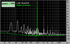
The 6AW6A – a single envelope high mu triode/pentode – met all the criteria. The experiment was simple. First, measure the triode half CCS-loaded and driving a resistor typical of a following stage's grid, in this case 160k ohm. The second half entailed buffering the triode's output with a cathode follower. In effect the triode is almost completely unloaded in the second.
The first circuit was:
- get a start on testing a big pile of 'unknown' tubes acquired as a gift a couple years back
- examine the effects of loading on a gain stage
- play around with pentode cathode followers.
The 6AW6A – a single envelope high mu triode/pentode – met all the criteria. The experiment was simple. First, measure the triode half CCS-loaded and driving a resistor typical of a following stage's grid, in this case 160k ohm. The second half entailed buffering the triode's output with a cathode follower. In effect the triode is almost completely unloaded in the second.
The first circuit was:
Attachments
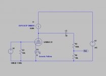
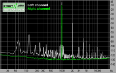
The 6AW6A's dirty harmonic profile made it a perfect candidate for the task. The results were surprising, at least to me. 160K would seem an easy load yet the CF cut the second harmonic almost to a third and slashed the upper harmonics in some cases by 15 dB. RightMark gives 0.18% THD and more incredibly under 0.2% IMD for the second case, even with the obviously dirty supply (a Titan Plus medical supply.)
A couple more observations, I spent a fair amount of time trying different cathode loads and operating points on the base CCS triode looking for the cleanest harmonic profile. The cathode follower however was a quick calc with no optimization. The design numbers targeted a 325 Vdc B+, however it was necessary to raise it to 345 to gain sufficient headroom. The second harmonic level wasn't much affected by the change but a upper ones saw a drastic reduction. A raw THD meter wouldn't have caught the difference but I'll lay odds an ear would have no problem. It's a possible clue to some of the bad reputation of CFs, without listening it's impossible to say.
Since this tube doesn't hold much promise I don't intend to spend much, if any, more time on it. I'm really interested however in examining further the split between voltage gain and current drive at an amp's front end. Next stop: a 6C45-pe followed by a either the same as a CF or a big output pentode as possible 813 front ends.
I bet it would've worked even better if the second half had actually been a pentode cathode follower. You needed to return the screen bypass capacitor to the cathode instead of connecting it to AC ground. What counts is the screen-to-cathode voltage. By not connecting it to the cathode, the screen voltage will actually vary even if the screen DC voltage-to-ground does not. The way it's set up, the pentode actually operates more like a triode since it's effectively a screen driven circuit.
rdf,
Thanks for the above. All design insights are valuable. I'm not surprised that the little extra voltage headroom slashed the higher order harmonics at 80 V pk-pk output. As a sweeping generalisation (of which you are probably already aware, this is for others benefit) harmonic distortions result whenever the output vs input deviates from a straight line. This can happen right through the range of inputs but is most obviously is going to happen at the extremes - that is when the tube tends towards cutoff (maximum positive output voltage peak) and when the tube tends toward saturation (maximum current and maximum negative going output peak). At these points the output vs input straight line rolls off to horizontal lines representing full saturation and full cutoff of the tube. The more abrubt or tighter the curve of these roll offs the higher the order of the harmonics which will be produced. The limiting condition - a square wave where if the tube is fast enough harmonics up into the 100s's can be produced.
So simply put - the closer you run a tube to cutoff or saturation, the higher order the harmonic distortion you are going to produce. (And the crappier its going to sound)
Miles' point above is worthwhile as well - pentode mode for cathode followers is much better (I can never remember the right spelling of the guys but was it Wallerman and Valley?? who showed the calcs to prove this)
Cheers,
Ian
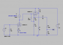
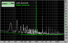
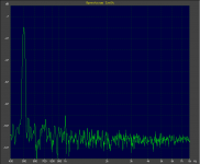
Thanks all! Miles, I understand your reasoning but not why it's 'more pentode'. From Kimmel's paper you're right and I obviously have some remedial reading to do. Following up on your suggestion, with the 8k ohm screen resistor the harmonic profile showed a nulled second harmonic and a wack of 3rd through ~ 7th, in my experience the signature of second harmonic cancellation. Sure enough, with the output superimposed on the screen it was being driven above/into the plate. Increasing the screen resistor to 33k ohm and raising the B+ ~350 to compensate did the trick. The distortion spectrum is shown below for the same operating conditions.
If I was a vague earlier the design of the original CF was rough at best - a few quick numbers and a minute with the plate curves - and the choice of tube literally random. It was intended as a proof-of-concept to determine how much even the slight current of driving ~150k ohm affected upper harmonics. As it was the original 'semi-pentode' appears to have been close enough. The new circuit changed little. THD is now 0.25% instead of 0.18%, suggesting the CF of the first circuit had slightly higher 2nd harmonic and a touch of cancellation occured. I'm certain a properly calculated design would likely yield better results. Next step is learning how to do just that.
Wavebourn: On the triode I tried multiple cathode loads including bypassed and unbypassed resistors, three different samples of the tube (all new RCA and all different), and operating currents from 3ma to ~6ma. The triode section's 1.1 watt limit narrowed the range of operating conditions. What you see is as good as it got and matched the manufacturer's recommendations surprisingly close. On the CF I tried almost nothing. 🙂 There's no question in my mind a CCS-loaded 6c45-pe or 12AT7A (according to SY) driving a properly calculated CF, say an EL38 perhaps, will absolutely trounce the results here.
Attachments
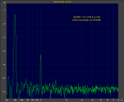
One more for fun. In the distortion spectra below an IR LED became the triode section's cathode load, the current through the CF lowered to about 7 ma, a small film cap went interstage (with these operating points the two stage voltages don't match) and the level changed to reflect use as a pre-amp, about 12 V p-p. Massive overkill for the application. A single second harmonic is visible above the noise at about 80 dB down, respectible for a no-GNFB, single tube, relatively low output impedance stage. I might have to tune the CF for direct coupling and look at building this one, even if I don't need a pre.
Attachments
That should read 6AW8A unloaded.
That would explain why I could not find the 6AW6 on any of my lists (warehouse collection) or in any of my books. The 6AW8 I have got, but haven't tried yet.
A few of years ago I wired up a test circuit for some of the common triode - pentode tubes. I found that I had far more tubes that used the same pinouts as the 6U8 than the 6AW8, so I went with the 6U8 connection. I tested for distortion and max output voltage of the triode when the pentode was used as a CCS load. I went through at least a dozen different types, deciding that the 6BL8 worked the best. I can't find the data now (poor organization then, before I even thought of making a web site).
I later discovered the CCS chip, and never went back to this circuit or the testing. I still have the test circuit, and will have to try it again.
Mild dyslexia is plenty entertaining, or so the business manager at work to whom I submitted eight operating budgets today would have me believe. On the bright side I haven't confused 0.0001 and 1000.0 volts yet.
Thanks for the idea, I discovered a pile of 6AU8A in my stock. Same pinout, trades higher triode power handling for lower pentode. Time to warm up the jig.
Thanks for the idea, I discovered a pile of 6AU8A in my stock. Same pinout, trades higher triode power handling for lower pentode. Time to warm up the jig.
- Status
- Not open for further replies.
- Home
- Amplifiers
- Tubes / Valves
- 6AW6A, Unloaded