Like many of the Munro models, it is not accurate, better make your own with CurveCaptor.
Color lines at 20V spacing vs Svelanta datasheet:
Color lines at 20V spacing vs Svelanta datasheet:
An externally hosted image should be here but it was not working when we last tested it.
Like many of the Munro models, it is not accurate, better make your own with CurveCaptor.
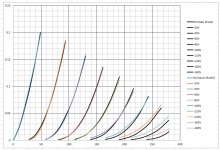
Color lines at 20V spacing vs Svelanta datasheet:
An externally hosted image should be here but it was not working when we last tested it.
I downloaded it, and it looks to be software written for mac users, all computers I have access to are Windows machines so I don't think I can run curve captor....
Googling the Multisim errors I'm getting is not giving me any substantive explanation of what is wrong.
I determined these values for the Koren model using jackinnj's method (Graph Grabber creates a csv file for Excel's solver function to work on)
mu 2.666592541
ex 1.322510698
kp 8.257298215
kg1 488.0839349
kvb 51.7599108
Errors are small in the region of most interest, Vp from zero to 200 volts and Vg > -100 volts. At high Vg and low Ip, the error is larger.
mu 2.666592541
ex 1.322510698
kp 8.257298215
kg1 488.0839349
kvb 51.7599108
Errors are small in the region of most interest, Vp from zero to 200 volts and Vg > -100 volts. At high Vg and low Ip, the error is larger.
Attachments
CurveCaptor is a Windows program. It needs a few associated programs which need to be installed before the program will run.
Yes, Jack's excel solver is another good choice, I wish people would stop using Koren or Munro's models, since they are usually not that accurate. They were the pioneers of tube SPICE models, but there are better tools and models these days.
Yes, Jack's excel solver is another good choice, I wish people would stop using Koren or Munro's models, since they are usually not that accurate. They were the pioneers of tube SPICE models, but there are better tools and models these days.
Last edited:
* Copy and paste from Munro 6AS7:
* Calculate reduction in mu at large negative grid voltages
* Emu mu 0 VALUE={PWRS(V(G,K),0.88)}
Just want to point out above math works, but not the way reality works.
Reduction in Mu is because many high Mu internal paths are in cutoff.
leaving only the lowest Mu subset of paths in operation...
I'm not saying the following is all there is to a good model, and its not
likely gonna be fast to compute 10 simple triodes in parallel. I'm missing
Miller, and grid current, and the lump above the zero line. Just saying
this alternative method explains reduction in Mu in a way closer to how
reality probably works...
This is AT7, anyone want to try bending these curves to fit an AS7?
.SUBCKT AT7 PLATE GRID CATHODE
.param MU0=35 PV0=.00015
.param MU1=40 PV1=.00016
.param MU2=45 PV2=.00018
.param MU3=50 PV3=.00020
.param MU4=55 PV4=.00025
.param MU5=60 PV5=.00030
.param MU6=65 PV6=.00035
.param MU7=70 PV7=.00040
.param MU8=75 PV8=.00045
.param MU9=80 PV9=.00050
G1 PLATE CATHODE VALUE={
+MAX(0,PV0*PWRS(V(GRID,CATHODE)+(V(PLATE,CATHODE)/MU0),1.5))+
+MAX(0,PV1*PWRS(V(GRID,CATHODE)+(V(PLATE,CATHODE)/MU1),1.5))+
+MAX(0,PV2*PWRS(V(GRID,CATHODE)+(V(PLATE,CATHODE)/MU2),1.5))+
+MAX(0,PV3*PWRS(V(GRID,CATHODE)+(V(PLATE,CATHODE)/MU3),1.5))+
+MAX(0,PV4*PWRS(V(GRID,CATHODE)+(V(PLATE,CATHODE)/MU4),1.5))+
+MAX(0,PV5*PWRS(V(GRID,CATHODE)+(V(PLATE,CATHODE)/MU5),1.5))+
+MAX(0,PV6*PWRS(V(GRID,CATHODE)+(V(PLATE,CATHODE)/MU6),1.5))+
+MAX(0,PV7*PWRS(V(GRID,CATHODE)+(V(PLATE,CATHODE)/MU7),1.5))+
+MAX(0,PV8*PWRS(V(GRID,CATHODE)+(V(PLATE,CATHODE)/MU8),1.5))+
+MAX(0,PV9*PWRS(V(GRID,CATHODE)+(V(PLATE,CATHODE)/MU9),1.5))}
R1 PLATE CATHODE 999G ; prevent floating nodes
R2 GRID CATHODE 999G ; pervent floating nodes
.ENDS
Last edited:
Well I figured out the 'magic trick' needed to make curve captor work on my computer, and if I have the captured data points of a curve I can make them into a SPICE model using the software...Only problem is that I don't have the captured data points for the 6AS7 curves, and I can't seem to figure out how to capture the data points from an image of the vintage data sheet curves without getting a "child killed:"(WTF?) error.
This is perhaps the least straight forward 'windows program' to install and use that I've ever encountered. I wanted a model of a 6AS7 to use in multisim so I could test my evolving design without continuously going to the trouble of building it in the real world, but just getting a working model of a 6AS7 is proving more time consuming and challenging then a few rewires of my semi-functional prototype.
If anyone can explain how to capture data points from an image of the curve without 'killing children'(egad what a weird name for an error!) then I'm all ears.
Last edited:
Sorry to hear the program is not running the way it should for you, please check the original thread to see how to fix the "child killed" error. Once you get it working, I think you will enjoy using it, I agree the installation procedure is a bit convoluted... you get what you pay for ;-)
Here is the model using Richard's optimized parameters:
.subckt 6AS7 A G K
+params: mu=2.666592541 EX=1.322510698 kP=8.257298215 kG1=488.0839349 kVB=51.7599108 VCT=0.00 ccg=6.8p cpg=11p ccp=2.3p rgi=2k
RE1 E1 0 1MEG ; dummy so node E1 has two connections
Ee1 E1 0 Value {(V(A,K)/{kP}) * log(1 + exp({kP} * (1/{mu} + (V(G,K)+VCT)/sqrt({kVB} + pwr(V(A,K),2)))))}
GIP A K Value {(pwr(V(E1),EX) + pwrs(V(E1),EX))/KG1} ; Norman Koren's
R1 G 5 {rgi} ; for grid forward current
D1 5 K DX ; for grid diode action
CM1 G K {ccg}
CM2 A G {cpg}
CM3 A K {ccp}
RF1 A 0 1G
RF2 G 0 1G ; prevent floating nodes
RF3 K 0 1G
* .MODEL DX D(IS=1N RS=1)
.MODEL DX D(Ron=1 Roff=1G Vfwd=0.75)
.ends
After REALLY scrutinizing the 6SN7 example posted in another thread and the curve captor interface I finally did figure out how to use curve captor. For those who are confused on how to capture data points in it and stumble upon this thread here is how you do it. Once you have loaded an image of the curves in the curve tracer tab set the increments on Vp to match the labels on your graph's plate voltage axis and use the mouse (and arrow keys for fine adjustment if needed) to place markers along the axis in the places that match your increments(start at zero). Once you have marked your voltage axis click on the Vp axis button and select Ip axis then mark the current axis using the same procedure as the previous axis(note the cursors look have changed). Once the Ip axis has been labeled click on the Ip axis button and select plate characteristics. These markers are not as constrained in the order you place them on the curve. Set the grid voltage of a curve you wish to trace and place several markers on it once done change the grid voltage and go to the next curve. While marking a given curve you can place markers on the curve in any order you like and can place additional markers between ones you have place if it seems appropriate. Practice helps, and saving work every several markers helps keep you from having to start from scratch to fix a mistake.
After getting curve captor to work I tried to get some of the the different spice models it makes to work in Multisim so far no luck, and after changing log in one of the models to log10(multisim don't like plain old log it seems) I managed to freeze up Multisim's convergence assistant.
Thanks! I'll give that a try.
After getting curve captor to work I tried to get some of the the different spice models it makes to work in Multisim so far no luck, and after changing log in one of the models to log10(multisim don't like plain old log it seems) I managed to freeze up Multisim's convergence assistant.
Here is the model using Richard's optimized parameters:
.subckt 6AS7 A G K
+params: mu=2.666592541 EX=1.322510698 kP=8.257298215 kG1=488.0839349 kVB=51.7599108 VCT=0.00 ccg=6.8p cpg=11p ccp=2.3p rgi=2k
RE1 E1 0 1MEG ; dummy so node E1 has two connections
Ee1 E1 0 Value {(V(A,K)/{kP}) * log(1 + exp({kP} * (1/{mu} + (V(G,K)+VCT)/sqrt({kVB} + pwr(V(A,K),2)))))}
GIP A K Value {(pwr(V(E1),EX) + pwrs(V(E1),EX))/KG1} ; Norman Koren's
R1 G 5 {rgi} ; for grid forward current
D1 5 K DX ; for grid diode action
CM1 G K {ccg}
CM2 A G {cpg}
CM3 A K {ccp}
RF1 A 0 1G
RF2 G 0 1G ; prevent floating nodes
RF3 K 0 1G
* .MODEL DX D(IS=1N RS=1)
.MODEL DX D(Ron=1 Roff=1G Vfwd=0.75)
.ends
Thanks! I'll give that a try.
Last edited:
Well Multisim does not like curve captor's spice models or your model. I'm starting to think Multisim has it's own version of spice and that it does not like any others. All I know about SPICE is that it is like VHDL for simulation of analog circuits(that is all college has taught me about it so far) so I'm not knowledgeable enough to debug the code. I think it is best I give up on simulating the outputs as I have already wasted more time then feel having a complete simulation of my design is worth to me right now.
In case your curious this is what Multisim thinks of your model...
------ Checking SPICE netlist for Reverse Futterman OTL 1.2 - Monday, July 22, 2013, 5:02:23 PM ------
SPICE Netlist Warning in schematic RefDes 'u1, u2', element 'dx': Unknown model parameter 'ron', this parameter will be ignored.
SPICE Netlist Warning in schematic RefDes 'u1, u2', element 'dx': Unknown model parameter 'roff', this parameter will be ignored.
SPICE Netlist Warning in schematic RefDes 'u1, u2', element 'dx': Unknown model parameter 'vfwd', this parameter will be ignored.
SPICE Netlist Warning in schematic RefDes 'u1, u2', element 'ee1': Use of log() is ambiguous, simulation will treat this as ln() in this case. See the "Mathematical Expressions" section in the Multisim SPICE manual for details
SPICE Netlist Warning in schematic RefDes 'u1, u2', element 'ee1': Use of log() is ambiguous, simulation will treat this as ln() in this case. See the "Mathematical Expressions" section in the Multisim SPICE manual for details
======= SPICE Netlist check completed, 0 error(s), 5 warning(s) =======
Error message from simulation: doAnalyses: Timestep too small
Error message from simulation: tran simulation(s) canceled
I was able to fix the log () errors by changing log () to log10 (), but the other errors remain. Some of the CurveCaptor SPICE code errors in multisim are nothing more descriptive then 'time step is too small'....Seeing that almost makes me think the code is fine, and Multisim is just giving me the finger to tick me off...Or somehow locked out of successfully adding components not in the database on my version.
I determined these values for the Koren model using jackinnj's method (Graph Grabber creates a csv file for Excel's solver function to work on).
As I mentioned, credit goes to Pierre Teouzelet (sp?) who wrote the article in AudioXpress -- we exchanged some emails (courtesy of Jan, and I did a little video on Youtube.
It's always important to keep the physics in mind with these phenomenological models.
Well Multisim does not like curve captor's spice models or your model. I'm starting to think Multisim has it's own version of spice and that it does not like any others. All I know about SPICE is that it is like VHDL for simulation of analog circuits(that is all college has taught me about it so far) so I'm not knowledgeable enough to debug the code. I think it is best I give up on simulating the outputs as I have already wasted more time then feel having a complete simulation of my design is worth to me right now.
Yes, incompatible SPICE syntax is one of the most irritating problems with circuit simulators, different vendors all have their own preference of which variant of the SPICE languages that they use. The issue you are having may have a simple fix by changing the following two lines:
.MODEL DX D(IS=1N RS=1)
*.MODEL DX D(Ron=1 Roff=1G Vfwd=0.75)
"Time step too small" seems to be an issue with the convergence, this requires some tweaking of the default values in Multisim, perhaps other users will have a better idea of what to do...
Well Multisim does not like curve captor's spice models or your model. I'm starting to think Multisim has it's own version of spice and that it does not like any others.
No one like National Instrument's pricing, but Multisim works very well for me.
SPICE Netlist Warning in schematic RefDes 'u1, u2', element 'dx': Unknown model parameter 'ron', this parameter will be ignored.
SPICE Netlist Warning in schematic RefDes 'u1, u2', element 'dx': Unknown model parameter 'roff', this parameter will be ignored.
SPICE Netlist Warning in schematic RefDes 'u1, u2', element 'dx': Unknown model parameter 'vfwd', this parameter will be ignored.
SPICE Netlist Warning in schematic RefDes 'u1, u2', element 'ee1': Use of log() is ambiguous, simulation will treat this as ln() in this case. See the "Mathematical Expressions" section in the Multisim SPICE manual for details
SPICE Netlist Warning in schematic RefDes 'u1, u2', element 'ee1': Use of log() is ambiguous, simulation will treat this as ln() in this case. See the "Mathematical Expressions" section in the Multisim SPICE manual for details
Just keep peeling back the spice directives until you have something which doesn't yield these errors.
And with regard to any data capture regimen -- you've got to eyeball the data -- this is what those Asiana pilots didn't do, they relied too heavily on their instruments and didn't bother to look out the window.
fwiw, there are some triodes that, by virtue of their construction, don't lend themselves easily to simulation. and with regard to tubes, the variability is so high that what you simulate may not come as close as you'd like to reality.
working on tetrodes and pentodes at the moment.
Errors are small in the region of most interest, Vp from zero to 200 volts and Vg > -100 volts. At high Vg and low Ip, the error is larger.
You can embellish the error modeling by only allowing values in the region of safe operation, i.e. set up a test such that the error is zero if the I(observed) * Vak > Maximum Power Dissipation.
Also -- helps if you have a lot more datapoints in the "region of most interest".
An externally hosted image should be here but it was not working when we last tested it.
Last edited:
- Status
- Not open for further replies.
- Home
- Amplifiers
- Tubes / Valves
- 6AS7 Model