So everyone is wrong then?
Everyone is a little bit right, and a little bit wrong.......Now that I have confused everybody.....
The turns ratio doesn't change. A 10K CT OPT iis 2.5 K from either side to the CT. This does not change it one tube, ten tubes or a pair of rotten tomatoes are connected up to it.
Connect up a pair of tubes running strict class A, and now there are two tubes sharing the same speaker. You could look at this as two totally independent class A amps each with a 2.5K to 8 ohm OPT feeding an 8 ohm speaker in parallel. Now visualize that 8 ohm speaker as a pair of 16 ohm speakers in parallel, then break the parallel connection and you have two separate amps each with a 2.5K to 8 ohm OPT feeding a 16 ohm speaker, which is like a pair of SE amps with a 5K load into an 8 ohm speaker. So it's not hard to see how the class A case results in a 5K load on each tube with a 10K P-P OPT.
Now lets look at the strict class B case. One tube feeds a 2.5 K OPT with an 8 ohm load while the other tube isn't there because it is cut off. Then the two tubes change position with no overlap. Each tube sees a 5K load.
Lets look at class AB.......there is no abrupt line in the sand (or should I say vacuum) where the 2.5K load instantly changes to a 5K load. If there was there would be some serious distortion at the transition because of the plate resistance in the tubes. There is a slow transition between the two APPARENT load impedances because the tube in cutoff has no Gm. As the current through the tube rises it's Gm rises from zero to its maximum while the other tube is headed toward cutoff, slowly losing it's Gm on the way.
There is a point in the middle where both tubes are conducting and both have some Gm. This overlap region gets wider as the idle bias on the tubes is raised, as does the Gm of BOTH tubes. The apparent load impedance seen by the tubes is the highest during the overlap region and is equal to HALF the total impedance of the primary ONLY at the point where the tube currents are equal. This equal load sharing is often called Gm doubling, but that isn't really the case since the tube current is less than what's needed for full Gm to be realized. yes the tubes are in class A and both conducting, so they are sharing the load, and they share it equally for a brief instant. Cranking up the bias current makes this sweet spot wider, and is the reason that amps sound better when the bias is cranked up.......
Piling on some feedback is another way to make the sweet spot wider since it increases the drive to the tube headed toward cutoff for a while on the way. Unfortunately the feedback runs out of the ability to do this rather abruptly creating higher order harmonics in the process.
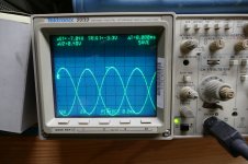
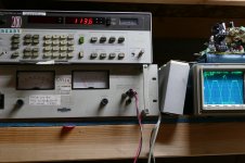
It is easy to see this process by sticking a small 1 ohm resistor in series with the cathode of each tube in a push pull amp. Then observe the cathode current waveform by connecting a scope across each resistor. You can see one tube turn off while the other is being driven. Then move the scope probes to the grids and look at what the drive signal does to get there. I couldn't find any cathode current pictures, but I did find some grid photos when I attempted to drive the grids out of some 6L6GA's.
The first picture show the drive signal at 60 watts out feeding a 3300 ohm OPT, about half what's recommended for a 6L6. The drive is a fat sine wave and one tube is obviously weaker and requires more drive. The grids are already being driven to +20 volts at this point.
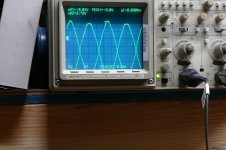
The next picture is at over 100 watts out. The drive to both tubes is being distorted by the feedback loop in order to correct for mismatched and overloaded tubes.
Next is the picture of the drive at 105 watts output just before it blew up. The THD out of the amp was under 5% but the drive signal to get there is ugly and different for each tube.
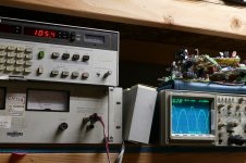
New cathode resistor, try again. THD is .4% power output is 10 watts.
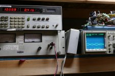
Crank it up.....113 watts output on 525 volts of B+, real ugly drive, blew up again, game over for that night.
Using tubes that are a little "over qualified" for the job will give you the best "design headroom".
Agreed, the testing above was an exercise in extracting over 100 watts from 6L6 tubes meant to produce at best 50 watts. Their little cathodes couldn't produce enough electrons to keep the "space charge cloud" filled thus inviting an arc through a depleted zone similar to secondary breakdown in a BJT.
Attachments
So push pull transformers are labeled and sold based on the class A region of operation and datasheets list it as an 'effective load resistance' instead of just a load resistance like they do for SE operation because that effective resistance relies on the opposing tube.
The load sharing in this class A region causes each tube to effectively see half of the load which doubles the Z for that particular tube allowing a 'real' Z of 2.5K to be 'seen' as 5K from the plate to the load.
The load sharing in this class A region causes each tube to effectively see half of the load which doubles the Z for that particular tube allowing a 'real' Z of 2.5K to be 'seen' as 5K from the plate to the load.
Last edited:
The load sharing in this class A region causes each tube to effectively see half of the load which doubles the Z for that particular tube allowing a 'real' Z of 2.5K to be 'seen' as 5K from the plate to the load.
If you do the turns ratio/Z computation it shows that 1/2 of the turns produce 1/4 of the Z, because the turns are squared in the equation. But you would never reverse a recommended 10K P-P OPT into a 2.5K SE OPT. Or in the case of a 6BQ5, a 6K P-P and believe that 1.5K is the appropriate Z for SE.
So push pull transformers are labeled and sold based on the class A region of operation and datasheets.....
?????
The OTs are marked as to what impedance they actually provide with their turns ratio from the specified load. (generally for P to P for P-P OTs) Up to you to decide which one you need. The data sheets give actual recommended loading too, although some adjustments may have been made from theoretical models due to spec or practicality constraints. Class of operation, and SE vs. P-P, makes for differences between the theoretical modes for the same type of tube. As does bias current level. A load line plotted on the tube curves (safely within the Plate dissipation and Screen dissipation limits) is the final say. You generally want the load line to intersect just above the knee of the grid1 = 0 curve, for the selected screen +Vg2. (so select screen V to achieve this) This keeps the screen grid from entering a high dissipation region when the tube is over-driven. (provided grid1 is not allowed to go positive, can clamp grid1 with a SS diode to cathode)
Last edited:
But you would never reverse a recommended 10K P-P OPT into a 2.5K SE OPT.
Indeed. The optimization for low 2nd Harmonic for SE and for low 3rd Harmonic for P-P lead to different solutions, without a nice simple relation between them. Although the equal loading scenario is probably good enough for an initial ball park when going from SE to P-P. Then OT reality and tube spec limits and screen grid current distortion will lead to some likely reductions in that Zprimary for P-P.
There probably would be a simple relation if the pentode case did not suffer screen grid current distortion. Which causes distortion to increase again at higher load Z. While triode mode monotonically lowers 2nd H at higher load Z.
A pentode -without- screen grid current distortion would just look like a high Mu triode.
Last edited:
Crank it up.....113 watts output on 525 volts of B+, real ugly drive, blew up again, game over for that night.
I had a 10R resistor burn up and turn into a 9K resistor yesterday. Idle current is 120ma.
Ohms law says the 10R resistor needs to dissipate 144mW at idle, but 4.9W at maximum signal (700ma, 1k3 RL-aa 6P45S triode). Perhaps using 10W parts will allow the test rig to survive higher testing levels?
The two windings of the primary are seperated by the filtering of the B+ and become a ground point to AC at the CT. No current from one tube ever travels through the other winding so it is basically non existant to each other. But the current through one winding half transfers magnetic energy to the secondary if the other is in cutoff.
The current travels through both halves and tubes. Like a capacitor keeps the voltage, the same way an inductance keeps the current. As I mentioned before, it is better to assume constant load between anodes of output tubes in PP, while the sum of their transconductances is variable, depends on the signal being amplified.
A tip:
Draw a straight load line through combined curves for PP. It would be better than trying to figure out the curved load line through single tube curves.
Draw a straight load line through combined curves for PP. It would be better than trying to figure out the curved load line through single tube curves.
That's probably the best compromise. We are making assumptions and designing amplifiers based on purely resistive loads of a fixed value, like 8 ohms.
The reality is that no speaker has a constant impedance and many will meet their published nominal impedance at one or two frequencies. A good speaker will have a published "impedance VS frequency" curve somewhere in the specs.
This curve was made with steady state sine wave tones at a low level, usually 1 watt. It is not valid at higher power levels, but usually close.
All measured data goes out the window when music is played through the speaker since the speaker is a two way device. It turns electrical energy into cone motion to create sound. It will also turn cone motion into electrical energy. Put a scope probe across your speaker terminals, then gently move the speaker cone. You will see a voltage generated in proportion to cone MOTION. The more violent the motion, the higher the generated voltage. Very efficient speakers can generate several VOLTS of signal if the cone is rapidly moved.
Lets suppose a large signal like a kick drum stomp is moving the speaker cone outward and while the cone is in motion a weaker signal like a human voice, hits the speaker attempting to reverse its motion. The cone is already moving due to the kick drum hit, and is thus generating a voltage (called counter EMF) which fights the voltage sent to the speaker by the amp. This makes the speaker's apparent input impedance lower.
If the amp is a large solid state amp with a near zero output impedance (high damping factor) the counter EMF will see a short circuit and not affect the amp's output. The speaker will receive all the energy that was in the signal fed to the amplifier.
Tube amps do not usually have a very high damping factor unless a lot of feedback is employed. This means that some of the counter EMF will be absorbed by the amplifier. The speaker's APPARENT input impedance at that instant in time will be lower than what's shown on the published impedance VS frequency curve.
To make matters worse there is a mechanical delay in the cone's motion such that the counter EMF is fed back into the amplifier a bit later in time than the signal that caused it. This causes some of the amplifier distortions that can not be measured by conventional means with resistive load testing, and adding GNFB can actually make matters worse because the feedback loop is trying to compensate for distortion not caused by the amp and delayed in time from the signal input to the amp. This counter EMF can be mixed with the new signal input creating IMD tones, creating output that is NOT in the amp's input. This has been called transient IMD, time smear, and a host of other audiophile words.
I set out to measure this dynamic impedance curve on my Yamaha NS-10M Studio Monitors several years ago. I convinced myself that the speaker can vary from 2 ohms to about 30 under dynamic conditions. That's when I discovered the time / phase delay aspect of the reflected EMF and realized that I did not have the means to measure it, or it's effect on the amp at the time. I may get back to those experiments some day, but they would likely prove that a speaker under some conditions can indeed exhibit negative input impedance (a power source stuffing energy into the amp) for instants of time under certain conditions.
We can demonstrate this with a DC motor and a flywheel. Apply a voltage from a power supply to the motor through a resistor. Put a scope across the resistor such that the current through the resistor is displayed, then instantly reverse the power supply. The motor will shove current into the power supply for the time it takes to reverse itself......Speaker cone = flywheel, voice coil + magnet = motor.
I didn't mean to feed the whole "we can hear things we can't measure" debate, just demonstrate that spending a whole bunch of time with load lines and math doesn't always translate to excellent sound. It is however the best approximation we have at the moment. Assume that the real load impedance seen by each tube in a push pull AB amp is somewhere between 1/4 and 1/2 the published transformer impedance and go with it.
I personally gave up load lines a long time ago. I simply test everything over a wide range of loads including extremes at both ends, and pick what works best. You don't need a bunch of OPT's, just one that is a bit oversized and a bunch of 1 ohm load resistors wired in series such that you can test with 1 ohm to maybe 20 ohms on the 8 ohm tap. You can then work backwards knowing the transformer's ratio to see what impedance you actually present to the tubes.
The point of maximum power and the point of lowest distortion will be different. If an FFT box (PC with RightMark) is available you can even look for the different harmonics. A tradeoff can then be made based on user preferences. If your test OPT has 0-4-8-16 ohm taps, then the number of resistors needed is reduced.
The current travels through both halves and tubes. Like a capacitor keeps the voltage, the same way an inductance keeps the current. .
But on the primary side, when one tube is in cutoff that side tube is like an open circuit or very high resistance so little current flows in its winding half. The stored energy does have a path through the secondary though so it dissipates through the speaker circuit.
But on the primary side, when one tube is in cutoff that side tube is like an open circuit or very high resistance so little current flows in its winding half. The stored energy does have a path through the secondary though so it dissipates through the speaker circuit.
Some of the energy in that part of the magnetic field collapse wud appear at the off plate. The part unhooked by the leakage reactance between the halves of the secondary.
Some of the energy in that part of the magnetic field collapse wud appear at the off plate. The part unhooked by the leakage reactance between the halves of the secondary.
My mind must be slipping out of gear, 86 today. Should be, the part unhooked by the leakage reactance between the halves of the primary!😱
My mind must be slipping out of gear, 86 today. Should be, the part unhooked by the leakage reactance between the halves of the primary!😱
Can you induce a lot of current through a coil with one end open? Does it create a meaningful parallel load to the active tube going high if the flux has the low resistance secondary in parallel to it like a low resistance resistor in parallel with a high resistance resistor? The flux energy is going to go out through the secondary.
Very little energy will be dissipated in the winding connected to the cutoff plate. The voltage on the cutoff plate will rise to a value approaching twice the B+ voltage when the amp is operating "normally." This means output below clipping and a resistive load. When the load is an electromagnetic device like a speaker, especially a speaker driven at its resonant frequency, and the amp is driven to clipping (a guitar amp), all bets are off.
I have measured over 2 KV on the plates of the 6L6GC output tubes in a guitar amp cranked well into clipping. The B+ in that amp was in the 425 volt range. Resonance occurs in the 100Hz region on many guitar speakers, which is in the range of frequencies generated by a standard guitar (82 to about 1Khz depending on number of frets). The speaker's impedance may be over 20 ohms at resonance, so the tubes and OPT will be lightly loaded. There could be a point in time where both tubes are cutoff due to bias shift from extreme overdrive allowing a flyback condition in the OPT.
These conditions should never bee seen in a sensibly operated HiFi amp, but I have been known to plug my guitar preamp int just about every amp I have ever made.......Cranked guitar through a SE 300B amp, yes and it survived. Cranked guitar through the first prototype of the SSE, and blew the screen resistors. This prompted me to use a bigger wattage part before it ever became a problem in the field.
Total cut-off would cause total (infinite) voltage.
In PP amp I shunt output tubes by damper diodes, to protect output transformers from overvoltage higher than 2xB+
You can safely run them into clipping without load attached.
In PP amp I shunt output tubes by damper diodes, to protect output transformers from overvoltage higher than 2xB+
You can safely run them into clipping without load attached.
I have not tried tube diodes, but some guitar players like the sound of an amp being pushed just short of blowing up. Silicon diode limiters kill some of that buzz saw sound. Again, not a problem in a normal HiFi amp, or 90% of the guitar amp / player combinations out there.
Wouldn't one need something at 2 x B+ to connect the damper (or SS) diode to? Those damper diodes only have around 25 Volts forward drop. Or is this going from plate to ground on opposite side of cutoff tube? (so limiting neg. swing thru xfmr)
Last edited:
You wire a diode or a series string of diodes from each plate to ground oriented so they should never conduct. In normal operation they won't. When one plate attempts to fly past 2X B+, the other plate must fly below ground, thus being clamped by the diode.
I imagine that this would stress the H-K breakdown in a tube, but some dampers have serious insulation. Who knows, I haven't tried it. SS diodes sound funny in heavy clipping, while gas tube lightning suppressors made for phone lines melt......
I haven't gone much further since a good OPT doesn't blow, usually an arc will start from pin 3 of the output tube to pin 2, either in the socket, or inside the base of the tube. I have seen such an arc blow parts connected to the heater circuit including a 12AX7. For this reason my high powered guitar amps got the heater circuit grounded, at pin 2, not elevated.
My mind must be slipping out of gear, 86 today. Should be, the part unhooked by the leakage reactance between the halves of the primary!😱
Happy birthday, and congrats!
I haven't gone much further since a good OPT doesn't blow, usually an arc will start from pin 3 of the output tube to pin 2, either in the socket, or inside the base of the tube. I have seen such an arc blow parts connected to the heater circuit including a 12AX7. For this reason my high powered guitar amps got the heater circuit grounded, at pin 2, not elevated.
In Ampeg SVT arcs retire tube sockets and hum-balance resistors. Output transformers often survive, looks like they have a good insulation. But since I use GU-50 tubes without such problem, and sweep or transmitting tubes with top anode caps, I have to protect output transformers.
Wouldn't one need something at 2 x B+ to connect the damper (or SS) diode to? Those damper diodes only have around 25 Volts forward drop. Or is this going from plate to ground on opposite side of cutoff tube? (so limiting neg. swing thru xfmr)
Yes, from plate to ground, SS damper diodes, reverse-parallel to tubes.
Last edited:
- Status
- Not open for further replies.
- Home
- Amplifiers
- Tubes / Valves
- 6AQ5 vs Other 7-pin Tube Dissipation Ratings