Couldn't find much on the net about this, but could a 6AL5 be used in place of the two diodes in a distortion pedal, such as a TS or any "insert popular distortion box here" circuit? Might have different clipping charactoristics if so.. and wouldn't requier a HV source for operation, only fils. Its also available from EH now apparently, for what reason I am unsure...
ThSpeakerDude88 said:Couldn't find much on the net about this, but could a 6AL5 be used in place of the two diodes in a distortion pedal, such as a TS or any "insert popular distortion box here" circuit? Might have different clipping charactoristics if so.. and wouldn't requier a HV source for operation, only fils. Its also available from EH now apparently, for what reason I am unsure...
Sure you can. The 6AL5 was designed as a high frequency, small signal dual diode (useful for making SB and DB passive ring mixers). No reason they won't work at AF. They will, however, require a volt or two of reverse bias. Silicon diodes don't turn on until the Vf rises to 0.7V. This gives you the clipping/limiting action.
hey thanks! I was a little worried about that... I thought that it might just plain act like a short and pull down the signal without some sort of reverse bias... can I just put a resistor in the cathodes , or will that only act like a more resistive short?
ThSpeakerDude88 said:hey thanks! I was a little worried about that... I thought that it might just plain act like a short and pull down the signal without some sort of reverse bias... can I just put a resistor in the cathodes , or will that only act like a more resistive short?
Your best bet would be a LED in series with each cathode for reverse bias. The AC impedance is quite low, and will hold off conduction better than a resistor. A voltage divider that puts a couple of volts on the cathodes might give a softer break. Depends on what kind of effect you're after here.
If I'd build a tube-distortion-box with a 6AL5, where do I put the 6AL5 ?
In a feedback loop (like in opamp-stompboxes) or at the output of a gain-stage, wired in anti-parallel to ground ?
Thanks,
Jim
In a feedback loop (like in opamp-stompboxes) or at the output of a gain-stage, wired in anti-parallel to ground ?
Thanks,
Jim
If I'd build a tube-distortion-box with a 6AL5, where do I put the 6AL5 ?
In a feedback loop (like in opamp-stompboxes) or at the output of a gain-stage, wired in anti-parallel to ground ?
Thanks,
Jim
You can actually do either, in the case of an output there should be a resistor between the clipper diodes and the op-amp..
You can also experiment with varying levels of reverse bias on the tube. Silver Oxide or alkaline watch batteries can be used in the cathode circuits to provide reverse bias in addition to the leds mentioned previously. More complex bias circuits would allow you to vary the point at which the 6AL5 starts to conduct. Leds can also make good clippers..
More complex bias circuits would allow you to vary the point at which the 6AL5 starts to conduct. Leds can also make good clippers..
How can this be done ? The bias circuit should have a high output impedance in order not to load the circuit, right ?
1. So would a watch battery have to be in series with each 6AL5 diode?
2. Would there be an advantage preceding the 6AL5 reverse parallel circuit with a cathode follower?
3. Has anyone out there made this work?
(Merlin has mentioned reducing filament voltage to change forward conduction point).
2. Would there be an advantage preceding the 6AL5 reverse parallel circuit with a cathode follower?
3. Has anyone out there made this work?
(Merlin has mentioned reducing filament voltage to change forward conduction point).
Soooo.... Nobody has actually made this work? 🙁
I tried it a few week ago, but without the reverse bias and it did not work very well. Put some led's in series with the cathodes but that didn't work either.
The 6AL5 was driven by an opamp, supply voltage 20V.
Will try this again later after I figured ou how to use the 6as6 as a distortion tube à la Culture Vulture.
1. So would a watch battery have to be in series with each 6AL5 diode?
2. Would there be an advantage preceding the 6AL5 reverse parallel circuit with a cathode follower?
3. Has anyone out there made this work?
(Merlin has mentioned reducing filament voltage to change forward conduction point).
Yes, watch battery in series with each cathode with + side to cathode, each series battery/diode combination can be connected back to back.
You can also apply variable bias to the diodes, this is a bit trickier, and works best with bipolar supplies and potentially a clutched pot.
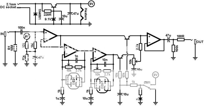
Something similar to what I have drawn will work..
Attachments
Last edited:
That looks hopeful.
I'm using +6.3v DC for my filaments. If I use two 10k pots across this with the wipers to the 6AL5 cathodes...or a zener and resistor... (and caps to block the DC as suggested)...
I'm using +6.3v DC for my filaments. If I use two 10k pots across this with the wipers to the 6AL5 cathodes...or a zener and resistor...
(and caps to block the DC as suggested)...Soooo.... Nobody has actually made this work? 🙁
Yep. The trick is to lower the heater voltage to between 3.5 to 4.5V, as this stops the reverse conduction you usually get at small negative Vak voltages.
Last edited:
Access denied
You are not authorized to access this page.
This site is run by unpaid, volunteer moderators, some of which have commercial interests in the guitar amplification business. They will all attempt to the best of their abilities to not interfere with commercial discussions. All messages on this forum express the views of the author and do not necessarily reflect the opinions of the site and (or) its administrators. This site will not be held responsible for the content of any messages posted on this forum. The operation of this site is supported financially by its members.
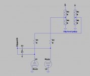
I was given several boxes of tubes recently - about 100 6AK5's and even more 6AL5's.
Have made a couple of single 6AK5 pedal-size preamps with big muff type tone control for my bass playing son and these are now part of his rig.
These are powered by a 9v 1A AC wallwart into a PCB 12v toroid (backwards for up to 200v dc once rectified and smoothed)
Attached is my attempt at getting sustain for my guitar with lots of even harmonics.
The 6AL5 provides limiting of the amplified signal and the cold biased 2nd 6AK5 does the soft even harmonic thing.
It needs some fine tuning but I'm getting close.
I think I need to move VR3 in front of the tone stack?
Can this type of tonestack be overloaded by too large a signal?
(and VR1 may become a Merlin inspired triode-pentode morph control).
I would also like to get the silicon diodes out eventually - the 6AL5 heaters are running at about 4v dc.
Any suggestions welcome.
JimG
Attachments
- Status
- Not open for further replies.
- Home
- Amplifiers
- Tubes / Valves
- 6AL5 for clipping diodes?