So this one goes below 80 Hz :^)?another 4 hours well spent 🙂
my first T.L, T.H ??
(what is the difference between a 'transmission line' and a tapped horn?)
initial listening tests on music are very good, it gets VERY low (much lower then the 'kuad kouppler"
and they're 8s, and different brands (i figure they will balance each other out)?
TL or TH lines can blur, and become a semantic difference, but looks like you built what would be called a TH.
Unlikely different types of speakers will "balance each other out" in the same tapped horn, but you may have gotten lucky.
In a dual 10 TH I built, I was surprised to find two of the same drivers, one with some added mass due to a cone repair, had hardly any more output at the same drive voltage than a single driver, level was about 1.5 dB up instead of the 6 dB gain when I put in a second normal driver.
In a ported cabinet, the combination of the normal driver and the added mass driver actually had a bit more LF than two normal drivers.
TH are "different".
A transmission horn?
A tapped transmission?
Two different drivers? Some times you just got to say WTF Risky Business style. The first part of the line looks like a transmission line with equal distance between the "leaves" the starts to flare half-way through to more a tapped horn.
Now to get anal DIY style and test that sucker out with tones and a SPL meter from Rad Shack. 😀 If it looks like your heart rate--you can stuff a little polyfill in the thing and see if it gets the bounces calmed down a little.
Think positive, nobody will ask for the Horn Response chart!
You forgot where we are... of course someone will ask 🙂Think positive, nobody will ask for the Horn Response chart!
how ever i did do the math on this one
Think positive, nobody will ask for the Horn Response chart!
Just do an alt/prtscreen of your hornresp input page and then paste into paintbrush.... I'm curious what your hornresp says compared to lilmike's with the anarchy? Also curious about your passive crossover...
An externally hosted image should be here but it was not working when we last tested it.
How is that doing the math on this one? Those are plans for the anarchy...
it was meant as a joke, i said *2* drivers 🙂
Can you post a schematic on the passive filter that's in there?
no idea ???
If this is representative:Can you post a schematic on the passive filter that's in there?

(2) 75ufd NP,
(2) 100mfd NP
(2 ) Coils ( oriented less than optimally )
About as cheap as it gets
If this is representative:
(2) 75ufd NP,
(2) 100mfd NP
(2 ) Coils ( oriented less than optimally )
About as cheap as it gets
So it's a 2 channel (probably meant for a dvc sub) 12 db @....something? From the size of those coils probably over 100 hz.
Are the 2 drivers that you put in that horn different drivers, 60ndown?
I'm guessing ( based upon specs of the similar units ) that the sub has a 12db rate and the satellites are 6db 1st order ( series cap ONLY )So it's a 2 channel (probably meant for a dvc sub) 12 db @....something? From the size of those coils probably over 100 hz.
Last edited:
your right, as cheap as it gets,12db and 6db, and it gets worse (or better),
the x over is intended for 8 ohm subwoofers, im using 4 ohm.
from other questions i have asked, using 4 ohm drivers with an 8 ohm *intended* xover, makes the slope and the x over point different, im guessing the subs are actually crossed over about 80hz and maybe 18db slope?
but as with all my audio projects, there is a lot of guessing, and a lot of fun.
there may well be a hole from 100-150 hz but i cant hear it.......
i decided to build is as my HT sub, something that would get really low (its tuned at 25hz) without having to be loud.
i noticed yesterday i could be talking on the phone and still have bass shaking my liver without disturbing the call
tonnes of fun 🙂
Last edited:
The xover frequency will be different, but a lower impedance requires a larger cap for 1st order HP....from other questions i have asked, using 4 ohm drivers with an 8 ohm *intended* xover, makes the slope and the x over point different, im guessing the subs are actually crossed over about 80hz and maybe 18db slope?
http://www.the12volt.com/caraudio/crosscalc.asp#ccc
The slope rate will be essentially the same.
Last edited:
...liver...
Hi 60ndown,
Nice to see you finally made a decision to get you started on tapped horn. One piece of advice though, you need to stop sitting on the horn mouth.
Regards,
Hi 60ndown,
Nice to see you finally made a decision to get you started on tapped horn. One piece of advice though, you need to stop sitting on the horn mouth.
Regards,
ill re read it
http://www.diyaudio.com/forums/multi-way/190200-what-effect-does-4-driver-have-8-ohm-crossover.html
http://www.diyaudio.com/forums/multi-way/190200-what-effect-does-4-driver-have-8-ohm-crossover.html
The xover frequency will be different, but a lower impedance requires a larger cap. The net effect will be to shift the fc upward, not down by an octave.
Passive Crossovers, Capacitor and Coil Calculator
The slope rate will be essentially the same.
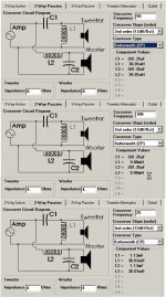
By doing a little "jammin" for a classic textbook topology:
it would appear that an fc of 200Hz was the original intent of the 8 ohm xover.
The 100mfd for the 6 db HP for the satellites
The sub 12db LP using a 9mh coil using 70mfd ( close to 75mfd standard value )
it would appear that an fc of 200Hz was the original intent of the 8 ohm xover.
The 100mfd for the 6 db HP for the satellites
The sub 12db LP using a 9mh coil using 70mfd ( close to 75mfd standard value )
Hi Y'all,
A quick and easy way to see what the xover will do is to use a simulator, this one is from Boxplot (look at the woofer sections):
Regards,
Wouldn't it be nice if a loudspeaker was similar to a resistor, then passive crossovers designed using a single value resistance would actually work properly.
I have yet to see a stock passive crossover acoustically do anything remotely like the predicted curve and crossover frequency it nominally is rated for.
To add to the fun, both of 60ndown's speakers loaded in his TH have different parameters, so each will have a different acoustic crossover . What the combined response is, is anybody's guess.
having been listening (and playing) music A LOT for 30 years, i can attest, the results in this instance are VERY good.
almost exactly what i wanted (room shaking lows at low volume)
i am thinking about another $35 tweak tho
i dont have one yet 🙂
equaliser | eBay
almost exactly what i wanted (room shaking lows at low volume)
i am thinking about another $35 tweak tho
i dont have one yet 🙂
equaliser | eBay
Filters ( 2nd order and above ) are combinations calculated for a particular "nominal" load....To add to the fun, both of 60ndown's speakers loaded in his TH have different parameters, so each will have a different acoustic crossover . What the combined response is, is anybody's guess.
The inductor values go up with increasing frequency; the reciprocal of caps whose values go down with increasing frequency. So impedance change is not being correctly compensated.
The transfer function could be determined by a sim program like Pspice.
Last edited:
- Status
- Not open for further replies.
- Home
- Loudspeakers
- Subwoofers
- 60ndown's Merged Subwoofer Thread