Hey Izozaya,
You were right! The LF351 latched and output was close to power rail pushing the output of the regulator down to nearly 5V. Could manually unlatch it by reducing the opamp power supply to a level that the regulator worked. Just wanted to test that the circuit worked, and it does!
I have an LM358 around so will hack the PCB to accommodate the different pinout.
Shouldn't take me long so hopefully will report progress this afternoon
Cheers,
Ale
Hey, it is not a problem if you have the correct analysis and know how to fix it. 🙂
See if you can give the opamp a bottom rail of -5V or so instead of tying the V- to GND. This will prevent the phase reversal problem and latch up.
Next improvements you might want to look at, are (1) using a DAC for setting the reference, and (2) improving the input offset error of the opamp (better precision at low Vout values).
Keep us posted!
Last edited:
Here's a little "fail-safing" for Ale's design -- from a SuperTex application note. The LND150's will only protect the opamp to 500V so another complementary set would have to be used.
I burned up some AD825's when first working with "The Art of Electronics" design, so this would reduce anxiety when power up the circuit.
An externally hosted image should be here but it was not working when we last tested it.
I burned up some AD825's when first working with "The Art of Electronics" design, so this would reduce anxiety when power up the circuit.
That´s a nice trick!
Also, you can alternatively use the AD629, but these are pricey and have limited bandwidth.
Also, you can alternatively use the AD629, but these are pricey and have limited bandwidth.
Chaps,
It works like a charm: 0-600v regulated. Have tested with a resistor load only. Will do more abusive tests later
Great!
Ale
It works like a charm: 0-600v regulated. Have tested with a resistor load only. Will do more abusive tests later
Great!
Ale
Hey jackinnj, that is a good suggestion, however PCB is made and no further room for any tweaks.
Today I did some more tests: capacitance load, shorts and excessive current dragging to ensure the current limiter was working.
Regulator is working just fine!
Here is final schematic:
http://www.bartola.co.uk/valves/wp-content/uploads/2012/10/600V-stabiliser-final.png
Thanks all for the help all along
Ale
Ale:
Am i reading this correctly? -- you're stimulating the input with 1V pk-pk on top of 600VDC which results in PSRR. You might want to stimulate the output with a few mA and a light load to get the output impedance and stability.
Am i reading this correctly? -- you're stimulating the input with 1V pk-pk on top of 600VDC which results in PSRR. You might want to stimulate the output with a few mA and a light load to get the output impedance and stability.
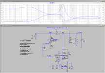
Hi Jack,
Like this? The output impedance seems below 30 ohms and exhibits a peak at 100kHz when regulating at low output voltages. Don't have the NPN model so didn't include the current limiter section. Not sure how much impact will have this part on the overall output impedance. Thoughts?
Thanks
Ale
Like this? The output impedance seems below 30 ohms and exhibits a peak at 100kHz when regulating at low output voltages. Don't have the NPN model so didn't include the current limiter section. Not sure how much impact will have this part on the overall output impedance. Thoughts?
Thanks
Ale
Attachments
- Status
- Not open for further replies.
- Home
- Design & Build
- Equipment & Tools
- 600V bench variable supply to test transmitting valves