It is normal with no load. However, under load the voltage drops much quicker than with solid state diodes.
You'll probably get around 400V (or less, it depends on the transformer and choke) at 100mA and around 330V at 200mA.
You'll probably get around 400V (or less, it depends on the transformer and choke) at 100mA and around 330V at 200mA.
It is normal with no load. However, under load the voltage drops much quicker than with solid state diodes.
You'll probably get around 400V (or less, it depends on the transformer and choke) at 100mA and around 330V at 200mA.
I will use one 5Z3 per channel.
I think with one 807 at 350v 75mA.
And the D3a driver tube with 150v 16mA.
And i will use a resistor about 100k in parallel with the caps filter.
Last edited:
E = I R
400 V = x A × 100,000 Ω
I = 4 mA
Not much added drain. The purpose of the resistor is mostly 'ceremonial': tp allow the capacitor stack to discharge in a reasonable amount of time, for safety. Good idea.400 V = x A × 100,000 Ω
I = 4 mA
Remembering RC is the 'time constant' of a capacitor('s) discharge, then
RC = 100,000 × ( 20 µF + 100 µF ) × 10⁻⁶ F/µF
RC = 12 sec
So, every 12 seconds, the voltage across the capacitors will drop by 1/e or 'multiply by 0.368' each 12 sec. Using 400 V:RC = 12 sec
400 → 147 → 54 → 20 → 7 → 2.7 → 1.0 V … in
0 s → 12 s → 24 s → 36 s → 48 s → 60 s → …
Recalling that e is Euler's or Napier's constant … 2.7182818…0 s → 12 s → 24 s → 36 s → 48 s → 60 s → …
________________________________________
I do not agree that 200 mA will drop the output by another 70 volts, unless the voltage drop is dominated by the resistance of the inductor instead of the rectifier tube. In my wan experience, a valve rectifier has a fairly “interesting” curve for output that isn't as 'bad' as a series resistance.
See last 2 pages of https://frank.pocnet.net/sheets/093/5/5U4GB.pdf
⋅-⋅-⋅ Just saying, ⋅-⋅-⋅
⋅-=≡ GoatGuy ✓ ≡=-⋅
Last edited:
Vcc is not the right term!, c stands for collector, this is a valve circuit. B+ is a common term used, as is V+.
Vcc notation comes from early logic IC's I believe, you see Vcc, Vee, Vdd and Vss for collector, emitter, drain and source in TTL and nMOS/pMOS/CMOS.
Vcc notation comes from early logic IC's I believe, you see Vcc, Vee, Vdd and Vss for collector, emitter, drain and source in TTL and nMOS/pMOS/CMOS.
The compatriot refers that VCC stands for "Volts Corriente Continua", or DC volts, as it is said in our language.
The compatriot refers that VCC stands for "Volts Corriente Continua", or DC volts, as it is said in our language.
Outstanding! I do believe however, that this is an English-preferred site, so that the most people might share each other's comments. Hence why the guidance of VDC over VCC remains good advice.
⋅-⋅-⋅ Just saying, ⋅-⋅-⋅
⋅-=≡ GoatGuy ✓ ≡=-⋅
Didn't you anytime do a mistake? So why can't anyone do it? In fact, it is a not too critical error and is clearly understood. Also the D and the C are very near in the keyboard. Perhaps a typo.
Didn't you anytime do a mistake? So why can anyone do it? In fact, it is a not too critical error and is clearly understood. Also the D and the C are very near in the keyboard. Perhaps a typo.
Señor Osalvo de Banfield, I think you are over-reacting to a constructive comment. (Reaccionar exageradamente a una crítica constructiva.) Of course we've all “made mistakes”.
Every one of us, every day, probably dozens of times.
May be more!
The correct term is VDC in English. And if it is a typo, then … the advice remains the same.
Have a good day!
⋅-=≡ GoatGuy ✓ ≡=-⋅
In fact my name is Osvaldo (From the german Oswald), not "Osalvo" 🙂 . My intention was only to acclare what I suppose the guy wrote.
Excuse my mistakes, I was talking about Vdc .. the original issue was if with a valve the voltage rise 1.41 when B + is not connected to anode, as it happens with diodes.
Yes. The main difference is that tube rectifiers have somewhat higher internal resistance and voltage drop, so, output voltage will be a bit lower than with SS rectifiers. But less noise.
Yes. The main difference is that tube rectifiers have somewhat higher internal resistance and voltage drop, so, output voltage will be a bit lower than with SS rectifiers. But less noise.
Thanks you Osvaldo.
What do you think ?
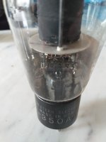
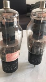
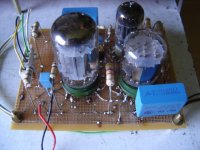
I am building a amplifier ,i have a 4.2K 40% OPT, one pair of Sylvania 6550 ( 40W dissipation ) and other pair of Western Electric 350A ( 28W dissipation ).
Could get 10W UL with the Western Electric 350A Beam Tetrode ?
According to WE is equal to 807 tube.
Attachments
Last edited:

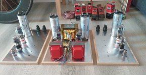
Osvaldo, that's alot of tubes for a monoblock especially compactrons which have 2-3 valves each. Those at the bottom of the photo look like horizontal outputs.
Yes, 8 multiple tubes per channel, plus 5 for the rectifier board (4 damper diodes 6AX3 plus a 6DJ8 (four diodes) plus a regulator with a 6K11 and a 6FM7 and 3 more for the delayed relay unit. A lot of heat, but performs very well near I ant from it. Fully DC coupled. In a PM I may send the schematic and lots of photos, but still unfinished and not sure if I will make it public here.
stocktrader₂₀₀;6176736 said:Osvaldo, that's alot of tubes for a monoblock especially compactrons which have 2–3 valves each. Those at the bottom of the photo look like horizontal outputs.
He's smart to use Compactrons, actually. The bespoke-valve-amplifier aficionados have glommed onto the “classics”, as well as the “improved classics” especially that sell at stratospheric prices appealing to otherwise relatively naïve 'tube and capacitor rollers'.
Compactrons by comparison, fit in nothing 'common'. Perfect! Really awesome tubes as well: basically the 'end of the design line' in the 1960s, when the valve makers were trying, trying, trying to invent valves that could surpass their older siblings, and compete handily with those darn upstarts, the transistors.
And they did. Handily. The annoying filament life (and power draw) still wasn't really an issue in 1965. People as innocently ignorant of electronics, but still handy with screwdrivers, could remove all the tubes from one's color TV, take 'em to the tester, get replacements and put 'em all back in a couple of hours on a Saturday morning, like my dear old Dad.
Couldn't do that with transistors, which for their first 10 years of commercial-to-consumer life, were no more reliable than valves, in many cases. Especially the 'power' transistors.
⋅-⋅-⋅ Just saying, ⋅-⋅-⋅
⋅-=≡ GoatGuy ✓ ≡=-⋅
And there are some very interesting combination of tubes in one envelope. For example, a 12AU7 plus a ½12AX7, with one power heater, 6.3V 600mA. One of the triodes is "free" of filament power. Also, I am working with the uncommon 6BF11, a compactron with one power section like a 6AQ5 plus a pentode like the 6AS6 or 6DT6. The pentode section performs excellent as a Schmitt trigger screen coupled, as the very unlinear characteristic of its screen and supressor make it ideal for signal signal conforming. Here is a little example.
My apologies by the off topic.
My apologies by the off topic.
Attachments
Last edited:
- Home
- Amplifiers
- Tubes / Valves
- 5Z3 How many VCC would have with 350VAC