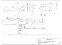
The layout diagram has voltages but not the schematic on this link: http://el34world.com/charts/Schematics/files/fender/Fender_CHAMP_5C1.pdf Make sure to pay attention to the -.5 volt bias on the 6SJ7's pin 4 since it's the old grid leak type and can be a different value for different tubes. That's why this type of bias was dropped in the '50s in favor of cathode bias for preamp tubes.
You could also reduce one of the input grid stoppers to ~30k or so to get more input signal for that jack allowing for two different gain levels. If you have some hum, you might want to reroute the heater wires away from the pre and power amp sockets.
You could also reduce one of the input grid stoppers to ~30k or so to get more input signal for that jack allowing for two different gain levels. If you have some hum, you might want to reroute the heater wires away from the pre and power amp sockets.
mmmm its a touchy little circuit swapped out the 5z2p-j Chinese rectifier for an OLD rca 5y3 lifted voltages thru amp by about 3 volts now i have a peek of 3 watts hum/hiss is milliwatts (ok i know this is not a high gain amp but its signal to noise ratio is the best I have ever built) would like to get it up to 5watts but will wait till i bring home my good dvm from work.
also i have a 6j8p-j in v1 (it is supposed to be an equivalent to 6sj7) may take sum tweaking
also i have a 6j8p-j in v1 (it is supposed to be an equivalent to 6sj7) may take sum tweaking
The original grid leak bias circuit worked OK (maybe) with fresh 6SJ7's of the day that had a good vacuum. Our 50+ year old stock today will have some gas leading to grid current. This upsets the bias. Many new production tubes are worse than the old stuff.......
Plug a stomp box into this amp and blast it with a few volts of signal, and you can prove that it's possible to have blocking distortion in the input stage.
I started out making 5C1's in the 60's using whatever tubes that I could find in the local trash dump. 6SJ7's were pretty easy to find, but 6V6's weren't, and many of then were bad, so I used TV sweep tubes. I had trouble with the input stage, low gain, distortion, and the dreaded blocking (farting out) when I fed the amp with my state of the art germanium fuzz blaster. A local ham radio guy told me how to convert the input stage to cathode bias, and most of the problems vanished.
I don't remember the parts values, but you put a resistor and bypass cap in series with the cathode, reduce the grid leak resistor to 100K or so, and ditch the input cap (short it out). This makes tube to tube variability far less, you can even run a 6SK7 (remote cutoff) to add some compression to the fuzz blaster, without blocking.
thanks for the input George, that's going to be my probable fix.
here are the voltages dc voltages with tubes in
V1 6J8p
1 0
2 heater
3 0
4 -001
5 0
6 23
7 heater
8 159
v2 rca 6v6gt
1 no con
2 heater
3 357
4 366
5 0
6 no con
7 heater
8 22
c1 369
c2 366
c3 344
using webber 5c1 schmatc
here are the voltages dc voltages with tubes in
V1 6J8p
1 0
2 heater
3 0
4 -001
5 0
6 23
7 heater
8 159
v2 rca 6v6gt
1 no con
2 heater
3 357
4 366
5 0
6 no con
7 heater
8 22
c1 369
c2 366
c3 344
using webber 5c1 schmatc
Attachments
Note that depending on what meter you are using, it will change the bias on the input tube when you measure the grid voltage, and the reading will not be accurate. The old vacuum tube voltmeters had a 10 or 11 meg input resistance. Most modern meters are lower. The $4 meters I get at Harbor Freight are about 1 meg. You are putting this in parallel with a 5 meg resistor, and the result is no longer 5 meg.
If you have 2 meters, put one on the plate and see how much the plate voltage changes when you probe the grid with the other meter.
Imagine a 10 to 12 year old kid trying to understand why the amp sounded better when I stuck my meter into it. The ham radio guy tried to explain it, but it wasn't being received too well at the time......I really didn't get the load line / impedance thing either, but that didn't stop me from making amps and blowing up tubes.
- Status
- Not open for further replies.