Hi all
Looking for a schematic for a headphone amplifier based off of a 5842.
I've built some "big" HP amps and looking for something smaller.
I initially thought of building this project DIY 6DJ8 (ECC88) Tube Hi-Fi Headphone Amplifier Project but 5842 may provide a more linear output and more power.
I've found a few links related 5842 but hoping someone can chime in with something they actually built that was sufficiently quiet for headphone use.
As another option, is it feasible to simply take the front-end of something like the Tubelab SE-II and simply connect it to the output (through a transformer) ?
Thanks
You mention the desire for a smaller amp. You could go hybrid for a smaller amp - reduce the enclosure and run frontend glass and backend mosfet?
I can't really give much more than that as I'm building my first.
I can't really give much more than that as I'm building my first.
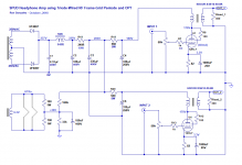
Cant remember where I found this but it was in my schematics collection 🙂
One of them adds an ultrapath capacitor and uses AC heaters. The other forgoes ultrapath probably because its using DC heaters to stop the hum.


The OPT specifies 32 ohms secondary but you can use one with 8 ohms too or any value thats under your phone impedance. As long as the impedance presented to the transformer is correct in the end. To do that an L type impedance matching network can be calculated here to match higher impedance headphones yet still presents the proper secondary impedance to the transformer be it 8, 16, 32, whatever. I use this handy-dandy calculator to match headphones to OPT's and see what various attenuations I'd get for all the valid match combinations of resistors in the L pad. For headphone amp building with an OPT Ive found this calculator a great help. You can even have a rotary switch that kicks in various L pads for different HP impedances, 32, 150, 300, 64, etc. In that mode a variety of headphones can all present the proper secondary impedance.
Network Calc
One of them adds an ultrapath capacitor and uses AC heaters. The other forgoes ultrapath probably because its using DC heaters to stop the hum.
The OPT specifies 32 ohms secondary but you can use one with 8 ohms too or any value thats under your phone impedance. As long as the impedance presented to the transformer is correct in the end. To do that an L type impedance matching network can be calculated here to match higher impedance headphones yet still presents the proper secondary impedance to the transformer be it 8, 16, 32, whatever. I use this handy-dandy calculator to match headphones to OPT's and see what various attenuations I'd get for all the valid match combinations of resistors in the L pad. For headphone amp building with an OPT Ive found this calculator a great help. You can even have a rotary switch that kicks in various L pads for different HP impedances, 32, 150, 300, 64, etc. In that mode a variety of headphones can all present the proper secondary impedance.
Network Calc
Last edited:
^ I think 5K:8 would actually be better considering the gain of the 5842. Just pay attention to the primary inductance of the output if you want good LF performance.
Network Calc
You also may be able to find one magic L pad resistor combination to support all phones from 32 to 600 and still present the proper impedance to the OPT. For example Ive had an Electra Print 5k to 40r 100ma transformer waiting for a headphone project. If I use 33r for the series resistor an 8r for the shunt with 300 ohm phones Im presenting a perfect 40.7 ohms, but if I plug 32, 64, 150 and 600 phones into the formula my presentation stays pretty much right around 40r, perfect. What varies then is the attenuation to the phones and the effective output impedance to the phones. Those are overcome by the volume control. In this case going from 300 ohm phones to 64 ohms moves the attenuation from 14 to 15, makes sense. But the main thing is the OPT is still seeing a 40 ohm load.
You also may be able to find one magic L pad resistor combination to support all phones from 32 to 600 and still present the proper impedance to the OPT. For example Ive had an Electra Print 5k to 40r 100ma transformer waiting for a headphone project. If I use 33r for the series resistor an 8r for the shunt with 300 ohm phones Im presenting a perfect 40.7 ohms, but if I plug 32, 64, 150 and 600 phones into the formula my presentation stays pretty much right around 40r, perfect. What varies then is the attenuation to the phones and the effective output impedance to the phones. Those are overcome by the volume control. In this case going from 300 ohm phones to 64 ohms moves the attenuation from 14 to 15, makes sense. But the main thing is the OPT is still seeing a 40 ohm load.
You could go hybrid for a smaller amp
I have a SS amp which I like, looking for compact tube-only build
What headphones will be used?
Specifically, what is the impedance rating for the headphones?
I mostly use 150/300 ohm headphones but I want this to be sufficient for a range of ~50-300ohm.
Cant remember where I found this but it was in my schematics collection 🙂
...
The OPT specifies 32 ohms secondary but you can use one with 8 ohms too or any value thats under your phone impedance.
Thanks for the schematic, I'll take a look.
I actually have 2 different 5K:8 transformers that I could use for this project, although they are a bit large.
I've used 5K:8, 5K:16 and 5K:32 successfully with headphone output with larger tubes, where I didn't strictly need an L-pad and still had sufficient power and the amp measured well (both in terms of THD and FR).
^ I think 5K:8 would actually be better considering the gain of the 5842. Just pay attention to the primary inductance of the output if you want good LF performance.
My only concern with 5K:8 is that I won't have sufficient output power with a range of headphones.
How much power does a 5842 have when its on its own?
^ 5842 is not going to handle plate dissipation more than a watt or so. Power output will be a fraction of dissipation. Maybe 1/4 watt or so output
See DHTRob websiteCant remember where I found this but it was in my schematics collection 🙂
Thanks jev.
For a such a small build, I would rather not use just a "standard" SE opt due to size/cost.
Any recommendation of a line transformer that could be suited for this?
For a such a small build, I would rather not use just a "standard" SE opt due to size/cost.
Any recommendation of a line transformer that could be suited for this?
itsikhefez,
. . . Line transformer, what kind do you mean?
Many do not work well with DC current, such as in a single ended output stage.
Look at the Hammond 125 SE series for single ended.
I have a 125DSE.
The problem with these is they do not have enough inductance, unless you use a really low rp tube. Without enough inductance the low frequencies are rolled off.
And, they can not put out very much power at low frequencies, not enough laminations.
But many headsets do not need much power.
Some paralleled dual triode tubes have fairly low rp. But then you need 2 dual triodes for stereo.
Or look at the smaller Edcor single ended transformers.
Now you know some reasons Marketing sold certain solid state amplifiers, small, light, inexpensive parts, and inexpensive to ship.
"All Generalizations Have Exceptions"
Last edited:
Thanks jev.
For a such a small build, I would rather not use just a "standard" SE opt due to size/cost.
Any recommendation of a line transformer that could be suited for this?
This site has some interesting and cheap options for small SE builds ...
Ask Jan First
6A3sUMMER,
I was referring to this similar HP 5842 design that uses the Lundahl LL1689 or LL1630
Hi-end headphone amplifier
Although it seems like the secondary winding of these transformers would be a bit too high for headphones in the 40-100 range.
I was referring to this similar HP 5842 design that uses the Lundahl LL1689 or LL1630
Hi-end headphone amplifier
Although it seems like the secondary winding of these transformers would be a bit too high for headphones in the 40-100 range.
^ 5842 is not going to handle plate dissipation more than a watt or so. Power output will be a fraction of dissipation. Maybe 1/4 watt or so output
According to a Raytheon data sheet I have, max plate dissipation for a CK5842 is 4.5W.
If you really get 0.25W output into a 32 ohm headphone load, then that should be overkill for most common headphones.
0.25W into a 32 ohm load would be 2.8V RMS.
(2.8V squared = 8V, divided by 32 = 0.25W RMS)
Most 32 ohm headphones have sensitivity of about 100dB SPL for 1mW drive.
250mW would be a LOT of drive power, to the point of over 120dB SPL (deafness inducing).
I think 0.1W (100mW) would be plenty for 100dB SPL/1mW sensitive headphones.
If you get 'only' a quarter watt from a 5842 into a 5k:8 OPT, then I'll bet you'd be fine.
BTW, I'm running a similar circuit using a 12GN7A in triode into an Edcor 8k:50 OPT, and it works fine. The stepdown ratio of the OPT (12.5:1) means it only gets about 2X gain, though. It's not enough to get crushingly loud with Sennheiser HD650 or (low sensitivity 60 ohms) Fostex T50RP, but it drives a more sensitive pair of Audio Technica ATH-M30 (70 ohms) to deafening levels, cleanly. Fortunately, I'm not looking to make myself any more deaf. 🙂
--
Last edited:
rongon, thanks for the info. Mind sharing that circuit?
I've just finished building an SE EL84 so I already have an amp that can make tons of power for headphones.... but it is large. I was looking to build something fairly compact.
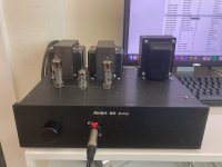
I measured close to 400mW @ 300ohms and 1.2W @ 100ohms on the 16ohm tap.
I've just finished building an SE EL84 so I already have an amp that can make tons of power for headphones.... but it is large. I was looking to build something fairly compact.
I measured close to 400mW @ 300ohms and 1.2W @ 100ohms on the 16ohm tap.
Attachments
Wow, yes, that is BIG for a headphone amp.
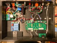
Mine is also large because it was built into a scrapped mono PP 6L6 amp chassis. It could be consolidated into a smaller chassis, especially if you use an isolation transformer and voltage regulator for the B+ instead of the choke input passive supply I used.
I tried it with LED cathode bias but found that I preferred the sound of the standard RC cathode bias.
The schematic shows 12HL7 for the tubes but I ended up using 12GN7A because I had a 12HL7 go bad and it was easier to find a pair of 12GN7A with matched gain. The circuit works pretty much the same with either.
This circuit doesn't get anywhere near 100mW out with the output from a typical DAC. There isn't enough gain. However, I can't get the thing anywhere near clipping without an additional gain stage in front of it.
--
Attachments
Looking to revive this thread, still interested in a 5842 headphone build.
I was thinking of using the Lundahl LL2766/30mA, with operating point of around 175V at 25mA bias.
Seems like 5K is typical primary for 5842, so I could wire the secondary with the 3k:16 option.
Reflected primary would be >6K for 32ohm and above headphones.
I can figure out the PS on my own, will probably use DC for heaters and some form of regulation or alot of passive filtering.
The main thing missing is just the basic schematic around the 5842
@rongon @Windcrest77
I've stumbled upon VTV issue 10 with Jack's Ultrapath Line Amp article, which give some more understanding on the DHTRob schematic above.
The current plan is to do some sort of variation of that scehmatic.
Some notes on the plan so far:
I'll be making a PCB for it, with most of the parts on it including volume pot and output jack to minimize wiring.
It could be adjusted for other triodes I assume.
Before I start spending time on a PCB, does this sound like a reasonable plan or would you suggest any changes?
I've stumbled upon VTV issue 10 with Jack's Ultrapath Line Amp article, which give some more understanding on the DHTRob schematic above.
The current plan is to do some sort of variation of that scehmatic.
Some notes on the plan so far:
- Edcor CXSE 5K:16 5W open-frame OPT (I have an unused pair)
- For B+, RCLC (as proposed by Jack in the same article)
- B+ 170-185V
- Hammond 269EX -- 380V C.T. @ 71ma. 6.3V @ 2.5A or
- Edcor XPWR024 -- 350V @ 60mA & 6.3V@2A
- Choke: 15H 350-400R
- Silicon diodes
- DC heaters, either CRC or use of a simple LM317 regulator.
- Ultrapath with Wima MKS or Kemet film caps ~50uF
- Single grid resistor, 100ohm thin film 1206 right at the tube socket
- Select cathode resistor for least distortion (using analyzer)
I'll be making a PCB for it, with most of the parts on it including volume pot and output jack to minimize wiring.
It could be adjusted for other triodes I assume.
Before I start spending time on a PCB, does this sound like a reasonable plan or would you suggest any changes?
Attachments
Hi itsikhefez,
I'm not sure why you need to use RCLC instead of the usual LCRC. Did you try both ways?
The power transformer should work with a choke input supply (LC). 190VAC * 0.9 = 171VDC
After that, you might consider a capacitance multiplier for ripple reduction without a lot of voltage drop.
A simple LM317 series regulator should do for the heaters. Two 5842 will require 6VDC at 0.6A. If you can get 9VDC unregulated and drop 3V across the regulator, that's 3V * 0.6A = 1.8W dissipated by the LM317. That won't require a large heatsink. Use an LT1085 or LT1086 regulator IC if you're worried about the dropout voltage (although 3V should be OK).
That said, I used AC heaters in my headphone amp and it doesn't hum at all. The amp has very low gain, so is less likely to pick up hum from the heaters. Twist the heater wires, route them away from the inputs, and be careful with lead dress around the tube sockets. The sticky thread "Heater Wiring - The Good, the Bad and the Ugly" is very good.
I think I'd wire the amp point-to-point to test it, before investing in PCBs. This circuit is so simple, it doesn't really need a PCB. Point-to-point wiring would allow you to change parts, make adjustments more easily than reworking a PCB.
How much plate current are you planning to have the 5842s draw? 10mA each?
- Home
- Amplifiers
- Tubes / Valves
- 5842 headphone amplifier