I have been working on a simple design for a turn on delay and DC protection utilizing the venerable NE555 timer and have encountered and interesting issue.
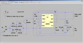
I decided to prototype the design quickly on some perfboard following simulation success. I only had a ratty old salvaged 555 chip that I wasn't even sure was OK, so I stopped at the local junk monger to pick up a few new ones. So, I cobble up the test circuit (see attached) with the recommended local decoupling and such and of course it didn't work as was expected (otherwise I wouldn't be asking 😉).
Well initially I can say my issue was self induced as I inadvertently applied a supply voltage that was too high and may have ruined one. After realizing my error I re-configured my PSU for a proper supply voltage and installed a new 555. Still wasn't working. Removed the second new 555 and double checked everything again, no errors found. I decided to pop in the ancient old 555 and here is where it gets interesting - the circuit worked exactly as expected.
OK, no apparent error. One possibly toasted 555 was my fault, another seemed to be DOA. Curiosity got me as I had bought four and had only tried two new ones thus far. I decided to try the others and found they did not work as expected either, but whenever the old one was inserted, voila, it would work.
Now to my question. Does anyone KNOW what, if anything, would cause three new 555s to not function (I actually found another unused one that did not appear to work either, so four in total) while the really old one worked perfectly? They are all bipolar devices, no CMOS ones were used. Is there some fundamental difference between the construction of the old vs new that is the difference? I thought the 555 was basically unchanged since 1970 so expected them to all behave the same. Am I wrong?
Attachments
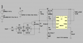
LTspice uses an idealized model for 555 timer. If you switch your simulation to the 555 model that properly simulates actual device, it won't work either. There is another representation of 555 timer implemented at transistor level in examples folder that came with LTspice.
In order to make your circuit work, you'll have to connect trigger and threshold pins together (pins 2 and 6). You'll also have to adjust RC values that define turn on delay, since the turn on sequence will now end at 2/3*VCC. Also make sure that the IC you're using can sink enough current through discharge pin, which you're using to drive relay (most datasheets don't specify maximum discharge current).
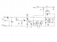
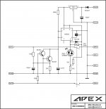
I'm attaching a schematic of protection circuit based on 555 timer that Apex uses with his amps. The circuit itself is based on the circuit used by Zeck Audio.
In order to make your circuit work, you'll have to connect trigger and threshold pins together (pins 2 and 6). You'll also have to adjust RC values that define turn on delay, since the turn on sequence will now end at 2/3*VCC. Also make sure that the IC you're using can sink enough current through discharge pin, which you're using to drive relay (most datasheets don't specify maximum discharge current).
I'm attaching a schematic of protection circuit based on 555 timer that Apex uses with his amps. The circuit itself is based on the circuit used by Zeck Audio.
Attachments
LTspice uses an idealized model for 555 timer. If you switch your simulation to the 555 model that properly simulates actual device, it won't work either. There is another representation of 555 timer implemented at transistor level in examples folder that came with LTspice.
In order to make your circuit work, you'll have to connect trigger and threshold pins together (pins 2 and 6). You'll also have to adjust RC values that define turn on delay, since the turn on sequence will now end at 2/3*VCC. Also make sure that the IC you're using can sink enough current through discharge pin, which you're using to drive relay (most datasheets don't specify maximum discharge current).
I'm attaching a schematic of protection circuit based on 555 timer that Apex uses with his amps. The circuit itself is based on the circuit used by Zeck Audio.
Fair enough about the idealized model, but why does the old device from the 1970's actually work as the idealized model while my newer examples do not?
From what little information I've seen about the discharge pin it would seem it can sink about the same as the output.
Thanks for the pointer to Apex's design, I have seen it before.
Have you actually tried fault-finding on the non functional chips to try and get an idea what is happening ? You've only one variable voltage to play with... try fixed levels and see if it works as expected. The 1meg, and I'm saying this for no good reason, could be too high... maybe 🙂
while my newer examples do not?Fair enough about the idealized model, but why does the old device from the 1970's actually work as the idealized model while my newer examples do not?
From what little information I've seen about the discharge pin it would seem it can sink about the same as the output.
Thanks for the pointer to Apex's design, I have seen it before.
Can you see the manufacturer logo on this?
Is it something no name?
The newest ones are Fairchild and the other one I didn't realize I had was a National Semiconductor (pre-acquisition). The oldie from the 1970's that works as per my original schematic is from Texas Instruments. I have no reason to believe any of them are fakes.
In any event I'm going to modify it to be more like the Apex example so it will work correctly with all examples of the device.
In any event I'm going to modify it to be more like the Apex example so it will work correctly with all examples of the device.
Fair enough about the idealized model, but why does the old device from the 1970's actually work as the idealized model while my newer examples do not?
From what little information I've seen about the discharge pin it would seem it can sink about the same as the output.
The device from 1970's works by pure luck, due to probably different implementation of internal flip-flop and its initial state compared to the "modern" devices.
Regarding discharge pin, an old application note from Phillips (AN170) specifies that the discharge pin is current limited at 35mA to 55mA internally. Contrary to this, TI's LM555 datasheet says that no discharge current protection is necessary provided that the package dissipation rating is not exceeded. So, once again this depends on the manufacturer.
Regarding idealized LTspice model, another difference worth pointing out is that LTspice 555 model has rail to rail output, contrary to the actual device, which does not.
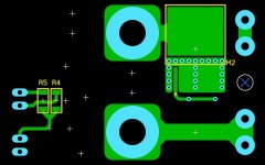
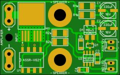
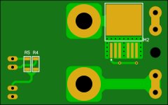
Continuing on, I have corrected the design and will alter the prototype for testing shortly. The idea is to make this a small PCB that will attach to standard dual binding posts with a 3/4" (19mm) spacing. At least that is the idea anyhow. That way it should be easy to add simple DC protection to designs lacking it already.
Attachments

Go ahead and try it with a 7555 and with a TS555 and with an LMC555 too. These are CMOS implementations and they have somewhat less macho "output grunt". They will tell you whether you've accidentally designed-in a requirement for hardsucking output pins.
The target current through the optocoupler is 20mA, so even the CMOS version should work, but you are right I will have to try it to be sure.
Anybody can make a turn-on time delayer. The trick is to make it so, if there is an interruption of AC power that only lasts for half a second, the turn-on delay function is reset virtually instantly, so that AC interuption doesn't cause a huge pop.
If the auxiliary PSU were integrated onto the board so it gets an AC supply, a 556 could be used to cut the SSR when AC is cut. I thought about this too and if I place a few of the low profile parts on the backside that might be possible too.
Hi Jason,In the last one, yes. One two pin connector for a bi-colour LED.
Great work, I am trying to make something similar based on apex audio schematics but integrated in PSU, see http://www.diyaudio.com/forums/soli...imate-fidelity-amplifier-542.html#post4465022.
Your idea of mounting on the speaker binding post is better. any progress with your work? were you able to solve the problem?
regards
Prasi
Last edited:
An extra transistor and three resistors can be added as a missing AC detector, D.Self shows this and it works. It's in one of the .asc I posted recently.Anybody can make a turn-on time delayer. The trick is to make it so, if there is an interruption of AC power that only lasts for half a second, the turn-on delay function is reset virtually instantly, so that AC interuption doesn't cause a huge pop.
The timing of this can be extended so that instead of triggering reset after one missing half wave, it triggers after 3, or 5, or 7, missing halfwaves.
Attachments
Last edited:
- Home
- Amplifiers
- Solid State
- 555 Timer DC Protect / Turn-On Delay