.
Has anybody built anything like this? Will the thing work?
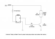
This is a 3-minute "delay on make" timer to energize a 24-volt relay, which switches power to a blower fan moter.
The circuit is turned on or off by a thermostat either suppling 24 volts or not. Once the circuit receives power and 3 minutes have passed, the relay is energized and remains energized until the thermostat turns off the 24 volts.
I imagine this will work after the NE555 has timed out and turned on the 2N222 transistor. Pin 3 of the NE555 will be at 12 volts, so the 2N222 will be at saturation, so the downsteam side of R1 will be essentially at ground. Under these conditions it won't matter that 24 volts is at the top of the relay-D1 combination. Or that's my guess.
But what about during the 3-minute time delay? I don't know what kind of voltages might be floating around. Does anybody have any experience or knowledge that they'd like to share?
PS: If anybody's interested, eBay will sell you both a "delay on make," or "delay on break," adjustable solid state timer relay for 10 bucks, including shipping. The same items go for a few bucks more on Amazon. But obviously I'd rather not go that way.
.
Has anybody built anything like this? Will the thing work?
This is a 3-minute "delay on make" timer to energize a 24-volt relay, which switches power to a blower fan moter.
The circuit is turned on or off by a thermostat either suppling 24 volts or not. Once the circuit receives power and 3 minutes have passed, the relay is energized and remains energized until the thermostat turns off the 24 volts.
I imagine this will work after the NE555 has timed out and turned on the 2N222 transistor. Pin 3 of the NE555 will be at 12 volts, so the 2N222 will be at saturation, so the downsteam side of R1 will be essentially at ground. Under these conditions it won't matter that 24 volts is at the top of the relay-D1 combination. Or that's my guess.
But what about during the 3-minute time delay? I don't know what kind of voltages might be floating around. Does anybody have any experience or knowledge that they'd like to share?
PS: If anybody's interested, eBay will sell you both a "delay on make," or "delay on break," adjustable solid state timer relay for 10 bucks, including shipping. The same items go for a few bucks more on Amazon. But obviously I'd rather not go that way.
.
Attachments
The combined V, R and C will not give you the 3-minute delay. Find the formula to calculate RC time constant. You will have to choose a practical threshold voltage which must match the output of your RC, otherwise it will trigger before the intended 3 minutes.
The combined V, R and C will not give you the 3-minute delay.
Thanks for your interest, and yes that's true. However, this circuit is what I guess you could call mature technology, and the values for any [reasonable] delay can be plugged in.
The unknown here is whether the NE555 working at 12 volts can successfully run as shown, activating the 24 volt relay. If anybody knows anything about this I'd be very glad to have the information. It will save me from polluting the atmosphere with vast amounts of magic smoke, and probably the EPA would start nosing around, which of course is something nobody wants.
.
I can't think of any reason why it wouldn't work. It may get rather inaccurate due to electrolytic capacitor leakage, but that has nothing to do with the relay-driving part.
If you were to use a CMOS 555 instead of a real NE555, you have to think if there is any chance that the current it draws goes to zero and the voltage drop across the zener becomes unpredictable. I don't expect that is any issue with a real NE555, though.
Is there any risk that the supply voltage may get stuck at some value in between 12 and 24 V for a long time, so that the transistor gets insufficient base current to fully switch on? If so, and if it is an insensitive relay, you may have to check the worst-case dissipation of the transistor.
I doubt that circuit will work. Just look at the datasheet of 555 and the applications given therein.
If you want a better timer, go for CD4541.
Gajanan Phadte
If you want a better timer, go for CD4541.
Gajanan Phadte
An RC for 3 minutes is very long - I don't think you can use a reasonable capacitor and resistor value for that. Check the data sheet.
A CMOS 555 may be better, or insert a counter to count, say 100 555-cycles of 2 seconds each.
Jan
A CMOS 555 may be better, or insert a counter to count, say 100 555-cycles of 2 seconds each.
Jan
.
MarcelvdG, thanks for your observations. It seems the votes have been counted--both of them--so all that's left to is try it.
I'm not certain what you mean by the supply voltage getting stuck. The NE555 draws some 10-15ma to run itself, which keeps the zener working, so I expect the supply voltage would remain at a [relatively] constant 12 volts.
The base voltage and/or current for the transistor is another story, that's a dark area to me. Well, shall see.
.
.
jan.didden, I agree that 3 minutes is pushing things for an NE555. But that isn't really the present question. The present question is whether an NE555 running at 12 volts can successfully switch a transistor running at 24 volts.
Returning to the 3 minute question, I'm ignorant on the subject of the CMOS 555, which was also suggested by MarcelvdG. Quickly adding that I'm ignorant, and I like it that way. I'm tired of learning about little black chips that you can't see inside of--or can't see at all, they're so small.
What was wrong with tubes--or as Europeans like to call them, valves? Nothing, if you ask me. The did the job, and what's more they kept the shack warm on a winter's eve.
In any case, there is such a thing as cascading 555s. Admittedly this solution:
1. Lacks elegance, and:
2. Is pretty shadetree.
But then:
1. So do I.
2. So am I.
.
.
I think it's fair for me to point out that commenting "I don't think it will work" conveys no real information. It only says that the person commenting doesn't know one way or the other, which is already why the original question was asked. It would be more accurate to just comment, "I don't know either," and let it go at that.
I mention this because I see a lot of such comments on these boards, almost always along with an instruction to go and look something up. Apparently on the assumption that the person asking the original question hasn't already tried to look something up, but has come to a dead end, and therefore is asking for help.
But "go look it up" is not help. In fact, it's the reverse, it's an announcement that "I won't help, it's up to you," which seems an odd thing to say.
If you're not going to help, then fine, you don't have to. But what does it accomplish for you to announce the fact in public? It would seem at least slightly more productive to say nothing, and save the monitor space for those who are willing to help. Less scrolling, if nothing else.
.
Specifically, from the section on that page caleld "Time Delay Circuits", this multistage 555 circuit can extend the delay by letting the first stage trigger the second to start to essentially double the delay. This is useful when capacitor leakage is a concern. I don't think that 3 minutes is out of the question, but you could use 6 of these in series, each doing 30 seconds if you want to be conservative.
An externally hosted image should be here but it was not working when we last tested it.
Also, keep in mind that the 556 is two 555 timers in a single DIP8 package. The 555/556 can drive a 12V relay coil directly (examples are on that page) so I would forget about the 24V relay and find a suitable relay with a 12V coil.
.
jan.didden, I agree that 3 minutes is pushing things for an NE555. But that isn't really the present question. The present question is whether an NE555 running at 12 volts can successfully switch a transistor running at 24 volts.
.
Of course it can.
If the switching transistor is NPN and the emitter tied to 0V with the relay as the collector load.
All the switching transistor needs is approximately 0.7V on its base relative to its emitter to switch on.
Three minutes is an impractically long time for a 555 period; consider the huge RC values involved and you will find that leakage currents dominate the behaviour of the system. It's inaccurate and unreliable.
If you want to run a long monostable like three minutes, run the the 555 astable at higher frequency (a few Hz) into a counter (e.g. CD4020) and choose one of the upper counter pins as your 3-minute output to the transistor+relay. You use the collector of the transistor pulling low to disable the 555 and halt counting once the output comes on. I've got a schematic somewhere around here that does this and even some spare PCBs that I packed into the corner of my previous fab run if you want one for the cost of postage.
If you want to run a long monostable like three minutes, run the the 555 astable at higher frequency (a few Hz) into a counter (e.g. CD4020) and choose one of the upper counter pins as your 3-minute output to the transistor+relay. You use the collector of the transistor pulling low to disable the 555 and halt counting once the output comes on. I've got a schematic somewhere around here that does this and even some spare PCBs that I packed into the corner of my previous fab run if you want one for the cost of postage.
The present question is whether an NE555 running at 12 volts can successfully switch a transistor running at 24 volts.
The 555 sees only the base of the transistor, not the 24V at the collector. It's totally fine as long as the switched voltage is within the Vce limits of the transistor.
Look at the typical low-side drive on a switching power supply. You have 5V logic driving the base/gate of an IGBT/FET which is switching perhaps 500V.
CD 4541 will give you timing from seconds to 10s of minutes.
In the 555 schematic you have drawn, the timing components(RC), I doubt they are interchanged.
4541 Timer Relay Circuit 0.3 second to 10 hours
Pin 6 should not be left floating. So connect a 10K resistor to +12V and short to ground as stated, there.
Gajanan Phadte
In the 555 schematic you have drawn, the timing components(RC), I doubt they are interchanged.
4541 Timer Relay Circuit 0.3 second to 10 hours
Pin 6 should not be left floating. So connect a 10K resistor to +12V and short to ground as stated, there.
Gajanan Phadte
555
I have used 555's in many applications, and they all worked flawlessly. The circuit you have shown looks like it will work OK.
Arv
.
Has anybody built anything like this? Will the thing work?
This is a 3-minute "delay on make" timer to energize a 24-volt relay, which switches power to a blower fan moter.
The circuit is turned on or off by a thermostat either suppling 24 volts or not. Once the circuit receives power and 3 minutes have passed, the relay is energized and remains energized until the thermostat turns off the 24 volts.
I imagine this will work after the NE555 has timed out and turned on the 2N222 transistor. Pin 3 of the NE555 will be at 12 volts, so the 2N222 will be at saturation, so the downsteam side of R1 will be essentially at ground. Under these conditions it won't matter that 24 volts is at the top of the relay-D1 combination. Or that's my guess.
But what about during the 3-minute time delay? I don't know what kind of voltages might be floating around. Does anybody have any experience or knowledge that they'd like to share?
PS: If anybody's interested, eBay will sell you both a "delay on make," or "delay on break," adjustable solid state timer relay for 10 bucks, including shipping. The same items go for a few bucks more on Amazon. But obviously I'd rather not go that way.
.
I have used 555's in many applications, and they all worked flawlessly. The circuit you have shown looks like it will work OK.
Arv
.
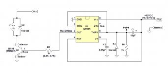
I lifted the NE555 equivalant schematic from Mitchekj, at the electronicspoint.com forums.
My poor brain lives back in the days when parts glowed and you could see inside them, as is right and proper. These opaque, sometimes near-invisible, black chips seem to me like something that slithered up out of the bad place. And what's wrong with ten percent distortion anyway?
Be that as it may, I puzzled through the schematic as best I could. Looking at the output, on the extreme right, it seems that pin 3 is connected either to ground, or to Vcc (supply voltage), depending on which transistor is turned on, Q22 or Q24.
Thus the base of an external transistor switched by pin 3 is either at ground, or at Vcc minus the voltage drop across the external transistor's base (bias) resistor. And all of this sure enough independent of whatever voltage might be applied to the external transistor's collector.
That's ignoring leakage, of course. Still, the votes, and the preponderance of the evidence, seem to indicate that yes, you can run an NE555 at 12 volts, and still switch 24 volts. Or anyway it looks good on paper. So I guess somebody should try it in the real world. I guess me.
OK I will, and will report back. But this will have to wait its turn while I rewire this ductless mini-split for non-computer operation--like there was something wrong with relays? But will do.
In a sidebar, what's this modern fashion of talking about "positive current flow"? Current flows against the arrows, everybody knows it, and that's an end to it.
.
Attachments
.
MarcelvdG, thanks for your observations. It seems the votes have been counted--both of them--so all that's left to is try it.
I'm not certain what you mean by the supply voltage getting stuck. The NE555 draws some 10-15ma to run itself, which keeps the zener working, so I expect the supply voltage would remain at a [relatively] constant 12 volts.
The base voltage and/or current for the transistor is another story, that's a dark area to me. Well, shall see.
.
Hi Picbuck,
Actually I wasn't suggesting that you should use a CMOS 555, but warning you that doing so might cause an extra problem if its supply current were to small to cause a predictable voltage drop across the 12 V zener. That's probably just me being paranoid, though. CMOS 555s definitely have the advantage that you can use larger resistors and smaller capacitors.
The part about the supply voltage getting stuck halfway refers to power brown-outs: there is mains voltage, but less than normal. Anyway, as long as your transistor can handle a power of one quarter of the power that the relay coil takes, it will always survive this condition.
The worst-case leakage specifications for electrolytic capacitors are usually too high for a 3 minute timer, but leakage tends to decrease more than linearly with decreasing voltage. Also, in my experience, leakage decreases far below the specified value when you keep them under voltage long enough. They stay at the low value if you then use them regularly. According to an old Siemens application note, long-life (LL) electrolytic capacitors leak less than general-purpose (GP) devices.
That is, assuming that you use an electrolytic capacitor, your 3 minute timer will probably work, but the delay might be 5 or 10 min if you start it up for the first time or after not using it for a long period of time.
Driving the transistor is no problem at all.
By the way, if you have such strong feelings about ICs and tubes, why don't you make a timer with tubes?
Best regards,
Marcel
- Status
- Not open for further replies.
- Home
- General Interest
- Everything Else
- 555 Timer Controlling a 24-volt Relay?