What I would do...
Replace the transistor with a 2N7000 (or other) FET. That eliminates the base resistor. The series zener is a "flaky" solution... not good even though it would work. CMOS 555's have been mentioned. Use one and with a series/shunt PSU (resistor and zener) to run the 555 on around 5 volts. The current consumption would be minimal.
Replace the transistor with a 2N7000 (or other) FET. That eliminates the base resistor. The series zener is a "flaky" solution... not good even though it would work. CMOS 555's have been mentioned. Use one and with a series/shunt PSU (resistor and zener) to run the 555 on around 5 volts. The current consumption would be minimal.
Let's All Say "Optocoupler"
.
Before anything else and most important, thanks for the links, input, and comments in this thread. Although, ahem, I think the suggestion for a tube-based timer might have been made slightly tongue in cheek, and, double ahem, the suggestion to cascade six NE555s more so. Not to say I don't do stuff like that.
To the present point, it turns out the Arduino crowd switches back and forth between low voltage and higher voltages all the time, and they use...tada...optocouplers, also called optoisolators.
True, this adds three or four components to the board, and also adds half a buck to the cost. But on the plus side optocouplers are made for this purpose specifically, and they're mature technology, which is what you want when it's August in Georgia and the air conditioner absolutely, positively, has to work, or you will not be a happy husband.
After all of which I will confess that maybe these observably hellspawn little back chips do have some good points. After all, you can put together a 20 watt amplifier with essentially no distortion for twenty bucks, including the power transformer. Nobody would have dreamed of this back in the day, and adjusting for inflation more so. OK then, I'll give them a good, firm maybe. But I'll be watching. And thanks again.
.
.
Before anything else and most important, thanks for the links, input, and comments in this thread. Although, ahem, I think the suggestion for a tube-based timer might have been made slightly tongue in cheek, and, double ahem, the suggestion to cascade six NE555s more so. Not to say I don't do stuff like that.
To the present point, it turns out the Arduino crowd switches back and forth between low voltage and higher voltages all the time, and they use...tada...optocouplers, also called optoisolators.
True, this adds three or four components to the board, and also adds half a buck to the cost. But on the plus side optocouplers are made for this purpose specifically, and they're mature technology, which is what you want when it's August in Georgia and the air conditioner absolutely, positively, has to work, or you will not be a happy husband.
After all of which I will confess that maybe these observably hellspawn little back chips do have some good points. After all, you can put together a 20 watt amplifier with essentially no distortion for twenty bucks, including the power transformer. Nobody would have dreamed of this back in the day, and adjusting for inflation more so. OK then, I'll give them a good, firm maybe. But I'll be watching. And thanks again.
.
I'm as much a fan of microcontrollers as anyone and use them regularly, but this is silly. An opto-isolator will work for sure but it's way more complicated and expensive than just using a transistor. Opto isolators are for when you don't have a common ground reference (high-side power switch), need safety isolation (switching PSU) or need to prevent capacitive coupling due to crazy slew rates (switching power inverter). None of that applies in any way whatsoever in this case because you have the relay for isolation purposes.
You wouldn't buffer a relay with another relay, so don't buffer your relay with an opto isolator.
.
Thanks for your comment, laplace, but I'm unable to see your point.
<< Opto isolators are for when you don't have a common ground reference (high-side power switch)... >>
I don't know what you mean by "high-side power switch," but taking the meaning from the context it seems to me that's exactly what I do have:
1. A 12 volt circuit running an NE555...
2. ...which is controlling a transistor used as an on-off switch...
3. ...which is switching a 24 volt circuit.
I have to admit I'm lost.
.
.
Thanks for your comment, laplace, but I'm unable to see your point.
<< Opto isolators are for when you don't have a common ground reference (high-side power switch)... >>
I don't know what you mean by "high-side power switch," but taking the meaning from the context it seems to me that's exactly what I do have:
1. A 12 volt circuit running an NE555...
2. ...which is controlling a transistor used as an on-off switch...
3. ...which is switching a 24 volt circuit.
I have to admit I'm lost.
.
What you have is a low-side switch because the transistor is between the load (relay) and ground. Therefore the transistor shares a common earth reference with the 555 circuit, which is all that matters. The two different supply voltages are entirely unrelated - you could run the 555 from 5V and put a 500V load on there if the transistor is rated for a Vce that high.
A high-side switch is where the switch is between the positive supply rail and the load, in which case it doesn't share an earth reference with the control circuit. That is the case where you need some sort of level-shifting circuit, e.g. an opto-isolator or a second transistor. For example if you're building an H-bridge for motor control, you need both high- and low-side switches, and therefore you need level shifters for the high side. The low side ones are wired directly though, as you should with this transistor.
You wouldn't put two relays in series (contacts of one powering coil of the second) because that would be pointlessly redundant. Likewise, using an optoisolator to isolate the relay coil is redundant.
Turns Out Yep, You Can
.
Thanks for your explanation, laplace. This set off a new round of surfing and research (read: the latest), and I see your point now. Especially regarding:
<< you could run the 555 from 5V and put a 500V load on there if the transistor is rated for a Vce that high. >>
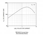
It turns out the aforementioned Arduino crowd--a wild bunch if ever there was one--use optocouplers only in the circumstances you mentioned. The rest of the time they seem to favor a TIP120 (max rating 3 amps at 60 volts) with a 1K base resistor.
The suspiciously small base resistor works because the TIP120 is a Darlington with enormous gain (1000+). Thus a 5ma current through the base resistor (5 volts / 1000 ohms) turns on the transistor without overloading the Arduino's output (max 40ma, as far as I can tell).
Google never forgets, so for other applications, for the benefit of future generations, I'm attaching the h-sub-f-e chart for a TIP120.
Thanks again laplace, and thanks again for the input of many. Proving once again that there's always a way, if you can only find it.
.
.
Thanks for your explanation, laplace. This set off a new round of surfing and research (read: the latest), and I see your point now. Especially regarding:
<< you could run the 555 from 5V and put a 500V load on there if the transistor is rated for a Vce that high. >>
It turns out the aforementioned Arduino crowd--a wild bunch if ever there was one--use optocouplers only in the circumstances you mentioned. The rest of the time they seem to favor a TIP120 (max rating 3 amps at 60 volts) with a 1K base resistor.
The suspiciously small base resistor works because the TIP120 is a Darlington with enormous gain (1000+). Thus a 5ma current through the base resistor (5 volts / 1000 ohms) turns on the transistor without overloading the Arduino's output (max 40ma, as far as I can tell).
Google never forgets, so for other applications, for the benefit of future generations, I'm attaching the h-sub-f-e chart for a TIP120.
Thanks again laplace, and thanks again for the input of many. Proving once again that there's always a way, if you can only find it.
.
Attachments
Yep. And a transistor as big as a TIP120 is only needed if you want to directly switch a moderate-sized load of an amp or two, e.g. a solenoid, light bulb or small DC motor. To switch a relay coil at maybe 70mA, you only need a BC546 or similar, which is a tiny and cheap device.
Don't forget the back-EMF diode across the coil or you will blow up the transistor when switching the relay off.
Glad you got it sorted.
Don't forget the back-EMF diode across the coil or you will blow up the transistor when switching the relay off.
Glad you got it sorted.
Correction
.
Thanks for your clarification, laplace, and a correction from me, just to keep things straight.
The TIP120 is rated for max 5 amps at 60 volts, not 3 amps at 60 volts as I wrongly stated.
Not that electronic components are ever to be used at their maximum ratings, of course. I personally like something around half, but I couldn't prove that two-thirds is wrong. After that...well...
.
.
Thanks for your clarification, laplace, and a correction from me, just to keep things straight.
The TIP120 is rated for max 5 amps at 60 volts, not 3 amps at 60 volts as I wrongly stated.
Not that electronic components are ever to be used at their maximum ratings, of course. I personally like something around half, but I couldn't prove that two-thirds is wrong. After that...well...
.
Ensure the switching transistor is saturated when driving the relay coil ON.
Find the coil current.
Divide by ~10.
This gives a good guide to the base current that must flow into the switching transistor.
If your coil current is 70mA I would suggest either a 200mA, or 500mA, To92 transistor.
Find the coil current.
Divide by ~10.
This gives a good guide to the base current that must flow into the switching transistor.
If your coil current is 70mA I would suggest either a 200mA, or 500mA, To92 transistor.
Super Alfa or Darlington pair.
High gain "a" driving power transistor "b".
Optocoupler is good if you are controlling a higher voltage with a low voltage control. IE an LED will operate at approx. 2 V.
You can get a Darlington transistor<<2 in one.
Or use an optocoupler as the driver of a Super Alfa pair.
If you don't get Full turn on of the transistor the volt drop across it will created wattage (heat)
Transistor burn out!
http://www.technologystudent.com/elec1/transis2.htm
NB don't forget your diode across the coil of the relay.. 😀 KISS...
Regards
M. Gregg
Last edited:
One other thing,
555 can be prone to noise.. particularly around relay or contactor switching.
Have you thought about SS relay? (I don't like them on safety critical applications)
Ref KISS (Keep it simple stupid).. 🙂
Regards
M. Gregg
555 can be prone to noise.. particularly around relay or contactor switching.
Have you thought about SS relay? (I don't like them on safety critical applications)
Ref KISS (Keep it simple stupid).. 🙂
Regards
M. Gregg
Last edited:
Hi picbuck,
in the 2nd schematic in reply #3, you note the power supply as 12V (6-18Vdc).
I just wanted to draw your attention to the 18V... This is over the specified maximum power supply voltage of several suppliers. The maximum is usually 16V. Your 18V is more than 10% over specified max and a potential problem depending on who made the 555 in use. Not good design practice!
In your first schematic, you feed from 24V through a 12V zener so that is OK on condition that the 24V does not become more than 28V.
Regards,
Luc
- Status
- Not open for further replies.
- Home
- General Interest
- Everything Else
- 555 Timer Controlling a 24-volt Relay?