the 5532 is not two 5534 tied side by side even with the capacitors area removed
1) It looks like the dual chip 5532 have some transistors in common
2) i couldnt find the equivalent transistors between the two chips...they look different
1) It looks like the dual chip 5532 have some transistors in common
2) i couldnt find the equivalent transistors between the two chips...they look different
Share an earlier solution, composed cascade dual match FET with NE5534
This has been an old forum in discussion NE5534, JFET OP which ones feature and performance is better long time ago.
Here, I would like to share the subject experiment I done 20 years ago. Using Cascade dual match JFET conjunction with NE5534 is indeed workable and function stable. The sound performance combined these two kinds OPA main feature without much parameter sacrificed. ( sorry, just by ear test that time)
I made a substrate PCB with an empty 8 pin socket and 5 pins hole socket, to easily plug in/ out device test. An Av=10 gain was set feedback to input inverter terminal . Non-inverter terminal just tied a resistor to ground.
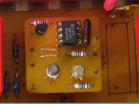
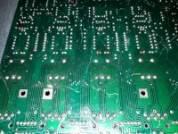
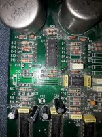
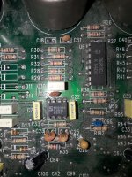
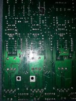
The composition of Cascade FET & NE5534 board, so called hybrid board, it is made by only 3x3 cm square, with 5 pins terminal. ( see fig 1, 2 following)
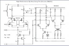
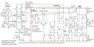
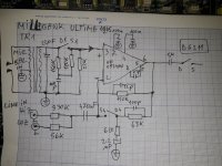
Hybrid circuit mainly follow the instruction of Siliconix appendix ( see fig.3 below), however, revised BJT constant current driven portion, substituting it by using a FET source follower~ by connecting a resistor between source and gate, minor adjusting the value of this resistor would decide constant current of first stage FET driving. Two drain resistors were connected with NE5534 Pin 1 and Pin 8 separately, Pin 2, 3 are connected to Vs- as an off function set.
The same hybrid boards have been deployed by several types, in order to compose with different device, i.e, LM318, LF351... like OPA627 internal circuit, with three stage signal driving and conversion. All of these effort was to try, figure out any better, compromised sound performance could be researched and also for experiment enjoy.
However, to reach such high standard sound quality, containing a mutual advantage of BJT and FET OP feature, certain extra, medium cost should be paid for. Dual match FET is expensive too.
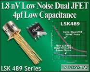
Especially, u401, 2N5911, LSK389/ 489.., these devices were made by BI-FET junction, with equivalent ultra low noise, low input capacitance, low input drift voltage parameter baring higher cost too. Fortunately, the cascade source follower dual match FET seemed no need to use Ultra low noise grade device. Using 2N3958, low cost unit should be good enough.
Under no signal situation, the output voltage is below 0.1V ( 100mV). By accurate adjusting the source bias into balance situation might help to reduce this output offset voltage. This also bear another extra work for parts pre-sorting, insert a tiny value of trim resistor setting.
Obviously, prototype sample making are always difficult to compete those industry mass process ( ie, laser trim process of OPA627) product. When engineer become hesitating doing this, time is money, people become to believe that using those high standard industry grade product is acceptable without doubt. Of course, when time goes by, next generation people will not remember what is NE5534 this device anymore.
The subject present an experiment, if you don't like or don't trust something, you have to face, to change it; nevertheless the result is good or bad, you have to proof and do that to convince yourself. The experience told me, this just for fun, nothing related to make money, when I was retired someday, I should remember all this process.
This has been an old forum in discussion NE5534, JFET OP which ones feature and performance is better long time ago.
Here, I would like to share the subject experiment I done 20 years ago. Using Cascade dual match JFET conjunction with NE5534 is indeed workable and function stable. The sound performance combined these two kinds OPA main feature without much parameter sacrificed. ( sorry, just by ear test that time)
I made a substrate PCB with an empty 8 pin socket and 5 pins hole socket, to easily plug in/ out device test. An Av=10 gain was set feedback to input inverter terminal . Non-inverter terminal just tied a resistor to ground.
The composition of Cascade FET & NE5534 board, so called hybrid board, it is made by only 3x3 cm square, with 5 pins terminal. ( see fig 1, 2 following)
Hybrid circuit mainly follow the instruction of Siliconix appendix ( see fig.3 below), however, revised BJT constant current driven portion, substituting it by using a FET source follower~ by connecting a resistor between source and gate, minor adjusting the value of this resistor would decide constant current of first stage FET driving. Two drain resistors were connected with NE5534 Pin 1 and Pin 8 separately, Pin 2, 3 are connected to Vs- as an off function set.
The same hybrid boards have been deployed by several types, in order to compose with different device, i.e, LM318, LF351... like OPA627 internal circuit, with three stage signal driving and conversion. All of these effort was to try, figure out any better, compromised sound performance could be researched and also for experiment enjoy.
However, to reach such high standard sound quality, containing a mutual advantage of BJT and FET OP feature, certain extra, medium cost should be paid for. Dual match FET is expensive too.
Especially, u401, 2N5911, LSK389/ 489.., these devices were made by BI-FET junction, with equivalent ultra low noise, low input capacitance, low input drift voltage parameter baring higher cost too. Fortunately, the cascade source follower dual match FET seemed no need to use Ultra low noise grade device. Using 2N3958, low cost unit should be good enough.
Under no signal situation, the output voltage is below 0.1V ( 100mV). By accurate adjusting the source bias into balance situation might help to reduce this output offset voltage. This also bear another extra work for parts pre-sorting, insert a tiny value of trim resistor setting.
Obviously, prototype sample making are always difficult to compete those industry mass process ( ie, laser trim process of OPA627) product. When engineer become hesitating doing this, time is money, people become to believe that using those high standard industry grade product is acceptable without doubt. Of course, when time goes by, next generation people will not remember what is NE5534 this device anymore.
The subject present an experiment, if you don't like or don't trust something, you have to face, to change it; nevertheless the result is good or bad, you have to proof and do that to convince yourself. The experience told me, this just for fun, nothing related to make money, when I was retired someday, I should remember all this process.
Attachments

Last edited:
Jim did you check your post?
It needs an edit !
It needs an edit !
Invalid Attachment specified. If you followed a valid link, please notify the administrator
Report your post to those people.
The last time I tried that I got a warning that I was misusing the report system. Different interpretation of the rules.
The last time I tried that I got a warning that I was misusing the report system. Different interpretation of the rules.
oop, I may mistaken deleted previous editing reply. I hope to edit thread #142 ONLY ~ To insert #143 circuit diagram combined with #142 would be much updated clear for reader.
Pin 5 is at one diode drop from pin 6(output) like for example at -420...430mV dc when the output is at +150mVLook at the NE5534 internal design. You will see that the PIN5 is the direct output of the internal VAS. That opens some possibilities like I mentioned before. You can use the PIN5 directly as output, and omit the class B output stage of the NE5534. The VAS will be mostly in class A. This output sounds far superior, but one must be sure that the current demand of the following stage isn't so big, and one must avoid shortcut's.
Second once like also mentioned before one can increase the class A range by adding a current source to pin 5 or simply a resistor from pin5 to V+
with kind regards,
Bas
I intend to use the pin 5 to drive a diamond buffer which makes thus reduced headroom.
I remember D Self headphones and lines preamps based on ne5534 and asymetrical buffers.Now I know why...cause you need to drive the output stage from a diode drop below the 0v output if you're going to use pin 5.
5534 is an excellent op amp for audio use. The key is to use reasonably low valued resistors in the circuitry around the op-amp, as the resistor noise can easily contribute more than what the op amp generates. It's a great little jellybean.
I don't think so. From audible view AD817 (used in Graham Slee MM-RIAA) or AD825 (LC-Technology favourised)5534 is an excellent op amp for audio use. The key is to use reasonably low valued resistors in the circuitry around the op-amp, as the resistor noise can easily contribute more than what the op amp generates. It's a great little jellybean.
provide clearly better sonic results in all applications. Maybe provided results for THD+N better on NE5534
The more I read about ne5534, the more I understand that very few designers are actually capable of using it the right way...
that means in reverse, most designers use the NE5534 in a wrong way.The more I read about ne5534, the more I understand that very few designers are actually capable of using it the right way...
But I don't understand this terms really:
"using it the right way" and "using it the wrong way"
5534 is not unity gain stable, so if using one is it at gains of less than I think it was 5x or so can lead to instability. External compensation is needed for operation at low gains. Check the spec sheet for details on this.


Well...it seems that decent recording equipment still use ne5532 today, including my Audient 22 in the mike preamp...When I bought it in 2017 I wouldn't know it's going to keep its price untouched for 6 years .Neve's using it in RNHP to drive TPA6120...Have you seen the technical reviews for them?
https://www.diyaudio.com/community/...-to-the-audiophile-world.348890/#post-6065578
https://www.diyaudio.com/community/...-to-the-audiophile-world.348890/#post-6065578
wee - this fact is usually only overlooked by beginners (currently at this days, unfortunately, more advanced electronics specialists, too).5534 is not unity gain stable, so if using one is it at gains of less than I think it was 5x or so can lead to instability. External compensation is needed for operation at low gains. Check the spec sheet for details on this.
- Home
- Amplifiers
- Solid State
- 5534 audio amp