Bruno Putzeys thinks the designer of the TDA1034 was:
Electronic Instrumentation Laboratory - People
Electronic Instrumentation Laboratory - People
Yes, and additional between the different brands of the NE5534. I recall, by the 741 a lot of different internal circuits was used. Also between the internal circuits of NE5534 are any differences (see attachement and datasheets)Would be interesting to objectively measure the differences between the Mullard TDA1034 (TO-99 metal can package) and the Signetics NE5534. Where to find these now ? - apart from dismantling the 1976 Pink Floyd mixing console ?
Unfortunately no internal circuit of TDA1034 I find.
TDA1034 Signetics
Download | Datasheet Archive
unfortunately without internal schematic
in German Elektor, November 1979 TDA1034 was describted:
"Topamp - Vorverstärker" (associated preamp for TOPAMP with OM931/OM961 from German Elektor October 1979)
an other application example you will find for driving a so called "new Class-A", (also in German Elektor):
Powered by Google Text & Tabellen
Here datasheets of NE5534 from various brands:
http://www.datasheetcatalog.org/datasheet/philips/NE_SA_SE5534_A_2.pdf (Philips)
http://www.datasheetcatalog.org/datasheet/texasinstruments/ne5534.pdf (TI)
NE5534 pdf, NE5534 description, NE5534 datasheets, NE5534 view ::: ALLDATASHEET ::: (ON)
?????????????????? (= http_semicon.njr.co.jp_njr_hp_productCategoryListFlip.do?_pageNum=2)
Attachments

Attachments
I second Jan's request - can you tell us more about his method?
The metod of Henk ten Pierick, well, he measures the jitter on high audio frequency signals caused by the low frequency signals simulaniously present. This is a rather difficult and costly measurement because of the needed jitter-meter. It seems that the human hearing is very sensitive to this phenomenon. The next question is: why should it be?
No, life is not that simple. There are different kinds of jitter - some are more important than others. Jitter caused by random noise is much less of an issue when compared to data-correlated jitter. Our brains are adept at picking out patterns and simple noise doesn't produce any.
OK about the data-correlated jitter, but this could very well be canceled by 'reclocking' the input-sinals to the DAC.
Random noise is still of interrest. Particularly the (random) noise very close to the carrier (within 10 Hz!) changes a lot! Eg. water 'sounds more wet' and other subjective (not measurable!) effects on the produced 'sound-stage'.
I'm working on good clock-oscillators already for years......
***********************
I doubt the 553x has any cross over distortion issues. Into a 600 Ohm load, this device produces around 5ppm distortion at 20KHz at 20Vrms. At very low output levels (few hundred mV) its still around 5ppm.
************************
5ppm = 106dB, modern OPamps have >120dB, so low that even an AP2 gets problemns to measure it directly. But I must say, that 90dB would be even so low, that you can't hear it.
The problem is the noise voltage in many prof. equipment. Think of an amplifier capable of generating 140Vrms output voltage. You MUST have at min. 120dB duynamic so that you can't hear noise out of the speakers if the signal is idle. (e.g. opera). With 4nV/sqrtHz it's a hard job to do (but it's possible)
The metod of Henk ten Pierick, well, he measures the jitter on high audio frequency signals caused by the low frequency signals simulaniously present.
OK thanks, very interesting😛 Is another way of describing this that he's measuring something to do with intermodulation? Jitter on a signal is the same as frequency or phase modulating it, is it not?
OK about the data-correlated jitter, but this could very well be canceled by 'reclocking' the input-sinals to the DAC.
Certainly that would deal with all kinds of jitter effectively with a very clean reclocking clock. I had an idea about somehow bit-stuffing the spare bits in the SPDIF dataframe with data inversely correlated. But this could only work with 16bit data and the receiving DAC would have to reject all bits beyond 16, so its fraught with difficulty unless both ends are controlled in the design.
OK thanks, very interesting😛 Is another way of describing this that he's measuring something to do with intermodulation? Jitter on a signal is the same as frequency or phase modulating it, is it not?
No! Methemetical you could perhaps transform the one into the other, but Henk persists in saying that he measures the jitter, and this is exactly what he does.
Raytheon had the best 5534 datasheet schematic, Fairchild acquired their product line and discontinued all opamps.
Huijsing has the best description of the 5534 inner workings in his book "Operational Amplifiers - Theory and Design", interesting to note that his description is followed by the design shortcomings imposed by the semiconductor process:
Huijsing p. 302
Huijsing has the best description of the 5534 inner workings in his book "Operational Amplifiers - Theory and Design", interesting to note that his description is followed by the design shortcomings imposed by the semiconductor process:
Huijsing p. 302
Attachments
Last edited:
Raytheon had the best 5534 datasheet schematic, Fairchild acquired their product line and discontinued all opamps.
Huijsing has the best description of the 5534 inner workings in his book "Operational Amplifiers - Theory and Design", interesting to note that his description is followed by the design shortcomings imposed by the semiconductor process:
Huijsing p. 302
And since the output stage is single Ended, you can transform it in a truth class A op-amp with a current source.
With kind regards,
Bas
The Raytheon 5534 seemed to sound best, back when it was available. Scott Wurcer should be an expert on what made it different.
As far as adding a fet input stage to the replace the bipolar input stage of the 5534. We built it up vertically as a 'cordwood module' so that the pins would only occupy the same surface area as the IC we were replacing. They DID sound better, but they were somewhat noisier.
It is true that the 5534 was a true improvement of most of preceding IC op amps in the mid '70's. Still, an A-B test against discrete showed differences.
The Raytheon 5534 seemed to sound best, back when it was available. Scott Wurcer should be an expert on what made it different.
As far as adding a fet input stage to the replace the bipolar input stage of the 5534. We built it up vertically as a 'cordwood module' so that the pins would only occupy the same surface area as the IC we were replacing. They DID sound better, but they were somewhat noisier.
It is true that the 5534 was a true improvement of most of preceding IC op amps in the mid '70's. Still, an A-B test against discrete showed differences.
Dear John,
Ever tried paralleling many Jfet's parallel on the input stage? I saw this once in a MIC preamp. They used a NE5534 with a whole bank of Jfet's as input-stage added on the comp pins.
With kind regards,
Bas
Raytheon had the best 5534 datasheet schematic, Fairchild acquired their product line and discontinued all opamps.
It's nice to see all the values on that schematic. I have to laugh at the JFET Q8... TI shows it too (I don't recall JFETs/BiCMOS back then) but it doesn't matter as it's just the current mirror reference.
Attachments
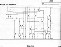
Even funnier, the NXP and ON datasheets erroneously show a PNP diff-amp whereas all the rest show NPN...
Even funnier, the NXP and ON datasheets erroneously show a PNP diff-amp whereas all the rest show NPN...
Isn't quite possible that the different manufacturers used different topologies?
jd
I am using NE5534A from TI in a shunt feedback arangement. 4 plus 4 in parallel. I tryed
LME49710 and other more recent designs but the NE gave the best result in this particular arangement. I whould be really surprised if the TI design is flawed in any way. Ship me a better variety and i try it out. For my design the NE has the best combination of low current and voltage noise and the circuit ( with a lot of feedback ) is very stable. The LME49710 has less voltage noise then the NE but 4 times more current noise so performance in terms of noise depends a lot on the source impedance. In my circuit the NE had the best balance.
LME49710 and other more recent designs but the NE gave the best result in this particular arangement. I whould be really surprised if the TI design is flawed in any way. Ship me a better variety and i try it out. For my design the NE has the best combination of low current and voltage noise and the circuit ( with a lot of feedback ) is very stable. The LME49710 has less voltage noise then the NE but 4 times more current noise so performance in terms of noise depends a lot on the source impedance. In my circuit the NE had the best balance.
Isn't quite possible that the different manufacturers used different topologies?
Unlikely for a drop-in replacement due to compensation and balance pins, balance pot wiper to V+ requires NPN inputs. Most commodity audio opamps like LM833 and MC34078 use PNP inputs, 5534 came before these.
Incidentally, NE5532 datasheets from NXP and ON show NPN inputs, so the 5534 schematics must be in error.
The JFET is probably an "epi-fet", in use since the 1960s.
Douglas Self coments about the Fet in his new book " Small Signal Audio Design " : " The biasing circuit shows an interesting point. Bipolar bias circuits tend not to be self-starting;
no current flows anywhere until some flows somewhere, so to speak, Relying on leakage currents for starting is unwise, so here the depletion-mode JFET provides a circuit element that is fully on until you bias it off, and can be relied on to conduct as the power rails come up from zero."
no current flows anywhere until some flows somewhere, so to speak, Relying on leakage currents for starting is unwise, so here the depletion-mode JFET provides a circuit element that is fully on until you bias it off, and can be relied on to conduct as the power rails come up from zero."
The circuit would not have worked with the very low beta of pnp transistors available at that time. Input bias current would have been too high
- Home
- Amplifiers
- Solid State
- 5534 audio amp