Now can you correct the wrong places in the diagram and send it to me? The diode isn't reverse like I said, is it?
Attachments
Does the Apex protection circuit DC protection works on both positive and negative rail DC in ouput?
I was testing the Dc protection with batteries , if + terminal is applied to Output and negative to ground then relay opens but if I swap polarity and supply negative to Output and + to Ground then nothing happens , can anyone tell why?
I was testing the Dc protection with batteries , if + terminal is applied to Output and negative to ground then relay opens but if I swap polarity and supply negative to Output and + to Ground then nothing happens , can anyone tell why?
When I did this protection, I used +15 and -15 from the power suply and it worked well.Does the Apex protection circuit DC protection works on both positive and negative rail DC in ouput?
I was testing the Dc protection with batteries , if + terminal is applied to Output and negative to ground then relay opens but if I swap polarity and supply negative to Output and + to Ground then nothing happens , can anyone tell why?
I also use a small transformer just for the protection circuit with +-15v bipolar supply, yes. I was testing the output providing dc voltage to the Dc protect and ground connections to the protection circuit and it works ok for +12 on amplifier output and - on GND but doesn't the other way around with - on the amplifier output and + on GNDWhen I did this protection, I used +15 and -15 from the power suply and it worked well.
did you also test the circuit with DC of both polarities to see whether he relay disconnects ?
Yes I did it with both polarities, but the Prot. has diferent sensibilitys. Dont forget to connect the GND protection, to main GND.I also use a small transformer just for the protection circuit with +-15v bipolar supply, yes. I was testing the output providing dc voltage to the Dc protect and ground connections to the protection circuit and it works ok for +12 on amplifier output and - on GND but doesn't the other way around with - on the amplifier output and + on GND
did you also test the circuit with DC of both polarities to see whether he relay disconnects ?
Yes of course the GND must be connected. How different are the sensibillity? Let me guess when - is connected to the output and + to GND it takes more volts DC to turn on the protection than when - is to GND and + to output?Yes I did it with both polarities, but the Prot. has diferent sensibilitys. Dont forget to connect the GND protection, to main GND.
Yes, is more or less like you said, but I dont remember because it was so long ago.Yes of course the GND must be connected. How different are the sensibillity? Let me guess when - is connected to the output and + to GND it takes more volts DC to turn on the protection than when - is to GND and + to output?
Is there any way for you to get a battery and test your circuit to know the voltages with one way polarity and the other way ?Yes, is more or less like you said, but I dont remember because it was so long ago.

i have 1 europower ep2000 damage too big on board i cannot repair so i was thinking make your b500 again inside it.
Great built, what PSU do you use ?? we do not see much in the video..look like you have just one Transfo and PSU for both B500
What is the recommended supply voltage for the Apex B50?Apex b50
If you like sound of B500, but is to much powerfull for Hi-Fi, consider about this 50W amp.
Regards
Dear Rohinapex b500 tef

I am from India Maharashtra
whear did you get that heatsink please help.
No point at all in going to 30kuF. 20k is the right value for 4 ohms load per channel - and that’s to get full power down to 20 Hz out of the amp. Any amplifier, it has to do with the time constant between the filter cap and the total load resistance. For top cab duty you could even get away with less since you don’t need full power down to 20 Hz.
The pole frequency is 4 Hz for 20kuF and 2 ohms (both channel load). The rule for getting “full power“ out of an amp at frequencies below the power line frequency is 5X away from the pole frequency. Below that the ripple voltage is excessive and reduces the max undistorted power to a noticeable degree.
The pole frequency is 4 Hz for 20kuF and 2 ohms (both channel load). The rule for getting “full power“ out of an amp at frequencies below the power line frequency is 5X away from the pole frequency. Below that the ripple voltage is excessive and reduces the max undistorted power to a noticeable degree.
Can anyone tell me ,
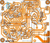
Who design this PCB because I am confused about, Apex sir layout and this PCB have little different is this B500P PCB or what.
Please help
And is this Heatsink ok for B500 mono
View attachment 1044775View attachment 1044774
Who design this PCB because I am confused about, Apex sir layout and this PCB have little different is this B500P PCB or what.
Please help
And is this Heatsink ok for B500 mono
View attachment 1044775View attachment 1044774
Hello Apex sir
I am confused between activ low pass filter and tone controller, which is used for amp input , I know active low filter is separate friquncy and so you didn't need passive low pass filter.
But which one used for amp input Because tone controller did not separate low, hi frequency but boost gain of all.
But all frequency go to all speakers on o/p.
Please clarify
- Home
- Amplifiers
- Solid State
- 500W PA amplifier with Limiter